
Page 280 - Engineering Digital Design
P. 280
6.3 DECODERS/DEMULTIPLEXERS 251
O G 0 D-
1 3 —
'o(H) 0 3-to-8 3 2 D-
1 Dec 4 D- " -Y 0-Y 7(L)
»;l^_
5 3 —
I 2(H) 2 6 >-
7 D-
— O G 0 D-
1 3 —
0 2 ^ —
3-tO-8 3 3—
(L 1 Dec 4 D- •Y 8-Y 15(L)
5 J-
2 6 D-
G 0 3 - - - - - 7 D-
0 2-to-4 1 •"\
1 Dec 2 D 1
I 4(H)
3 D ) l_ — c G 0 D-
1 3 —
0 2
3-to-8 3 ^ D-
1 Dec 4 0- Y 16-Y 23(L)
5 Q^
2 6 0-
7 o-
— o G 0 D-
1 D-
0 2 2
3-tO-8 3 D- •Y 24-Y 31(L)
1 Dec 4 D-
5 D-
2 Q D-
7 3-
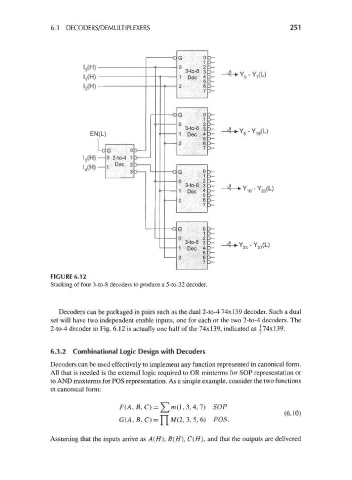
FIGURE 6.12
Stacking of four 3-to-8 decoders to produce a 5-to-32 decoder.
Decoders can be packaged in pairs such as the dual 2-to-4 74x139 decoder. Such a dual
set will have two independent enable inputs, one for each or the two 2-to-4 decoders. The
2-to-4 decoder in Fig. 6.12 is actually one half of the 74x139, indicated as \74x139.
6.3.2 Combinational Logic Design with Decoders
Decoders can be used effectively to implement any function represented in canonical form.
All that is needed is the external logic required to OR minterms for SOP representation or
to AND maxterms for POS representation. As a simple example, consider the two functions
in canonical form:
,C) = y/n(l,3,4,7) SOP
£^ (6.10)
G(A, B,C) = M(2, 3,5,6) POS.
Assuming that the inputs arrive asA(//), B(H), C(H), and that the outputs are delivered