
Page 276 - Engineering Digital Design
P. 276
6.2 MULTIPLEXERS 247
KL)
L-C
<) (H) u G
\= H 'o
BC
0 1 11 10 1(H) I, Y(H)
00 1 4-to-l V
C D 1 — \T~X- i MUX O-Y(L)
1 — }l^~ '2
D C © D C + D rX^-s^ y 1 _/""""
^~\sr j '' ] ^/
'3
Y
(b) (c)
A(H) B(H)
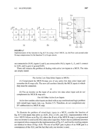
FIGURE 6.7
Implementation of the function in Eq. (6.7) by using a 4-to-l MUX. (a), (b) First- and second-order
K-map compressions for the function Y. (c) Logic circuit.
are connected to D(H), inputs /5 and /6 are connected to D(L), inputs /2, h, and 7 7 connect
to !(//), and /o goes to ground 0(//).
There still remains the problem of dealing with active low inputs to a MUX. The rules
are simply stated:
For Active Low Data Select Inputs to MUXs
(1) Complement the MUX K-map axis of any active low data select input and
renumber the K-map cells. The new cell numbers identify the MUX inputs to which
they must be connected.
or
(2) Use an inverter on the input of an active low data select input and do not
complement the MUX K-map axis.
For All Other Active Low Inputs
Active low nondata select inputs are dealt with as any combinational logic problem
with mixed-logic inputs (see, e.g., Section 3.7). Therefore, do not complement any
EV subfunction in a MUX K-map.
To illustrate the problem of mixed-logic inputs to a MUX, consider the function of
Eq. (6.7) with inputs that arrive as A(/f), B(L), C(H), and D(L). Implementation with a
4-to-l MUX follows as in Fig. 6.8, where the B axis of the MUX K-map is complemented
since no inverter is used on the B(L} data select input line. Notice that no additional inverters
are required when compared to the implementation of Fig. 6.7, and that the resulting outputs
are identical to those of Eqs. (6.8). The use of an EQV gate in place of an XOR gate is a
consequence of the D(L) and the fact that only one inverter is used.