
Page 278 - Engineering Digital Design
P. 278
6.3 DECODERS/DEMULTIPLEXERS 249
EN(L)
u G 3— Y 0(L) = m 0EN(L)
YO
Y D—Y 0(L) = m 0EN(L) D— Y 1(L) = m 1EN(L)
*1 Y 1 — Y 1(L) = m 1EN(L) 1-to-2" Y ^ D—Y 2(L) = m 2EN(L)
2
, n-tO-2" Y 2 p-Y 2(L) = m 2EN(L) G DMUX :
Decoder
(Decoder) '
D— Y 2n_ 1(L) = m 2n. 1EN(L)
^2"1
Y n D—Y 2n. 1(L) = m 2n. 1EN(L)
2 -1
G
a O .. . C O 0
n-l °2 l ^0
(a)
n Data-Select
Inputs
(b)
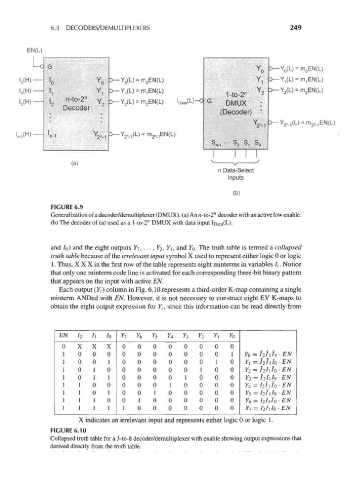
FIGURE 6.9
Generalization of a decoder/demultiplexer (DMUX). (a) An «-to-2" decoder with an active low enable,
w
(b) The decoder of (a) used as a l-to-2 DMUX with data input loata(L).
and /o) and the eight outputs Y-j, ..., ¥2, Y\, and YQ. The truth table is termed a collapsed
truth table because of the irrelevant input symbol X used to represent either logic 0 or logic
1. Thus, X X X in the first row of the table represents eight minterms in variables //. Notice
that only one minterm code line is activated for each corresponding three-bit binary pattern
that appears on the input with active EN.
Each output (Y/) column in Fig. 6.10 represents a third-order K-map containing a single
minterm ANDed with EN. However, it is not necessary to construct eight EV K-maps to
obtain the eight output expression for 7,, since this information can be read directly from
EN h /i /o Yl Y 6 Y 5 *4 Yl Y 2 Y\ Yo
0 X X X 0 0 0 0 0 0 0 0
1 0 0 0 0 0 0 0 0 0 0 1 YQ = /2/1/0 -EN
1 0 0 1 0 0 0 0 0 0 1 0 YI = I 2i \IO-EN
1 0 1 0 0 0 0 0 0 1 0 0 Y 2 = l 2I\h-EN
1 0 1 1 0 0 0 0 1 0 0 0 Y 3 = I 2IiIo-EN
1 1 0 0 0 0 0 1 0 0 0 0 Y 4 = i 2i \IO-EN
1 1 0 1 0 0 1 0 0 0 0 0 Y 5 = i 2i \IO-EN
1 1 1 0 0 1 0 0 0 0 0 0 Y 6 = I 2lJ 0-EN
1 1 1 1 1 0 0 0 0 0 0 0 Y 1 = hhh-EN
X indicates an irrelevant input and represents either logic 0 or logic 1.
FIGURE 6.10
Collapsed truth table for a 3-to-8 decoder/demultiplexer with enable showing output expressions that
derived directly from the truth table.