
Page 282 - Engineering Digital Design
P. 282
6.3 DECODERS/DEMULTIPLEXERS 253
Then by Eqs. (6.11) and if inverters are not to be used, the B and C bits must be comple-
mented:
mo = 000^011 =m 3 ra 4 = 100^ 111 = m 7
m, = 001^010 = m 2 ra 5 = 101 -> 110 = m 6
m 2 =010-^001 = mi m 6 = 110-> 101 = m 5
m 3 =011-»000 = roo m 7 = 111 -> 100 = m 4.
Thus, to accommodate the mixed-logic inputs, the two functions in Eqs. (6.10) must be
connected to the decoder according to the renumbered functions
m
2 4 7 and
F[A(H), B(L), C(L)] = J2 (°' ' > >
G[A(H),B(L),C(L)] = Y\M(Q, 1,5,6).
Of course, if inverters are used on the B(L) and C(L) inputs, no complementation is
necessary and the functions are implemented according to Eqs. (6.10).
Decoders, used as demultiplexers (DMUXs), are simply reoriented so that the active
low enable is the only data input. Now the // inputs become the data select inputs 5, as
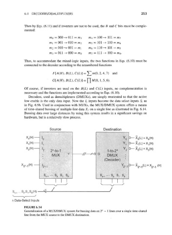
in Fig. 6.9b. Used in conjunction with MUXs, the MUX/DMUX system offers a means
of time-shared bussing of multiple-line data X t on a single line as illustrated in Fig. 6.14.
Bussing data over large distances by using this system results in a significant savings on
hardware, but is a relatively slow process.
Source Destination
X 0(H) 3— X 0(L) = X 0(H)
ID Y 0
X,(H) Y 1 3— X 1(L) = X 1(H)
"1
X 2(H) 2 n n Y2 3— X 2(L) = X 2(H)
' 2 -to-1 1-to-2
: MUX Y ff so G DMUX :
•
(Decoder) '
_1<H) — Y 3-X 2n. 1(L) = X 2n
' 2 M
o o o o s ,-s s
^n-1 '" *z *1 ^0 n 2Sl 0
n Data-Select Inputs
FIGURE 6.14
Generalization of a MUX/DMUX system for bussing data on 2" — 1 lines over a single time-shared
line from the MUX source to the DMUX destination.