
Page 283 - Engineering Digital Design
P. 283
254 CHAPTER 6 / NONARITHMETIC COMBINATIONAL LOGIC DEVICES
6.4 ENCODERS
By definition an encoder performs an operation that is the opposite to that of a decoder.
That is, an encoder must generate a different output bit pattern (code) for each input line
that becomes active. For a binary encoder, this requirement can be enforced only if one
n
output binary word of n bits is associated with only one of 2 "decimal" input lines
(0, 1, 2, 3,..., 2" — 1). Obviously, if more than one input line is active, the output be-
comes ambiguous in such an encoder. The ambiguity problem is overcome by prioritizing
the input. When this is done the result is called a priority encoder (PE), which assigns a
priority to each input according to a PE schedule for that encoder. Most encoders are PEs.
m
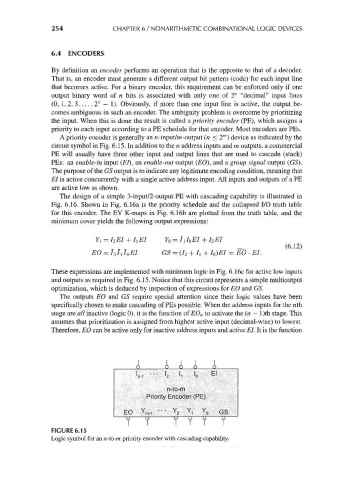
A priority encoder is generally an n-input/m-output (n <2 ) device as indicated by the
circuit symbol in Fig. 6.15. In addition to the n address inputs and m outputs, a commercial
PE will usually have three other input and output lines that are used to cascade (stack)
PEs: an enable-in input (El), an enable-out output (EO), and a group signal output (GS).
The purpose of the GS output is to indicate any legitimate encoding condition, meaning that
El is active concurrently with a single active address input. All inputs and outputs of a PE
are active low as shown.
The design of a simple 3-input/2-output PE with cascading capability is illustrated in
Fig. 6.16. Shown in Fig. 6.16a is the priority schedule and the collapsed I/O truth table
for this encoder. The EV K-maps in Fig. 6.16b are plotted from the truth table, and the
minimum cover yields the following output expressions:
7i = I 2EI + 7, El FO = I\ loEI + I 2EI
_ (6.12)
EO = 7 2 /i I 0EI GS = (I 2 + /i + Io)EI = EO • EL
These expressions are implemented with minimum logic in Fig. 6.16c for active low inputs
and outputs as required in Fig. 6.15. Notice that this circuit represents a simple multioutput
optimization, which is deduced by inspection of expressions for EO and GS.
The outputs EO and GS require special attention since their logic values have been
specifically chosen to make cascading of PEs possible. When the address inputs for the nth
stage are all inactive (logic 0), it is the function of EO n to activate the (n — l)th stage. This
assumes that prioritization is assigned from highest active input (decimal-wise) to lowest.
Therefore, EO can be active only for inactive address inputs and active El. It is the function
A A A A
n-to-m
Priority Encoder (PE)
EO Y m_, — Y 2 Y, Y 0 Gs
7 r
FIGURE 6.15
Logic symbol for an n-to-m priority encoder with cascading capability.