
Page 279 - Engineering Digital Design
P. 279
250 CHAPTER 6 / NONARITHMETIC COMBINATIONAL LOGIC DEVICES
EN(L)
u G Y 0
—
1° 3-to-8 Y 3
, Decoder y
EN(L)-c[>
(b)
I I "—I 1 1—7*—\ V V /I \
'o(H)-
EN(H)
i—ft ^/
Y 7 (L)
(a) (c)
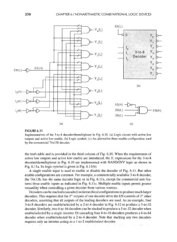
FIGURE 6.11
Implementation of the 3-to-8 decoder/demultiplexer in Fig. 6.10. (a) Logic circuit with active low
outputs and active low enable, (b) Logic symbol, (c) An alternative three-enable configuration used
by the commercial 74x138 decoder.
the truth table and is provided in the third column of Fig. 6.10. When the requirements of
active low outputs and active low enable are introduced, the 7, expressions for the 3-to-8
decoder/demultiplexer in Fig. 6.10 are implemented with NAND/INV logic as shown in
Fig. 6.1 la. Its logic symbol is given in Fig. 6.1 l(b).
A single enable input is used to enable or disable the decoder of Fig. 6.11. But other
enable configurations are common. For example, a commercially available 3-to-8 decoder,
the 74x138, has the same decoder logic as in Fig. 6.1 la, except the commercial unit fea-
tures three enable inputs as indicated in Fig. 6.1 Ic. Multiple enable inputs permit greater
versatility when controlling a given decoder from various sources.
Decoders can be stacked (cascaded) in hierarchical configurations to produce much larger
m
decoders. This requires that the 2 outputs of one decoder drive the EN controls of 2" other
decoders, assuming that all outputs of the leading decoders are used. As an example, four
3-to-8 decoders are enable/selected by a 2-to-4 decoder in Fig. 6.12 to produce a 5-to-32
decoder. Similarly, two 4-to-16 decoders can be stacked to produce a 5-to-32 decoder when
enable/selected by a single inverter. Or cascading four 4-to-16 decoders produces a 6-to-64
decoder when enable/selected by a 2-to-4 decoder. Note that stacking any two decoders
requires only an inverter acting as a l-to-2 enable/select decoder.