
Page 292 - Engineering Digital Design
P. 292
6.5 CODE CONVERTERS 263
D 4(H) D 3(H) D 2(H) D l(H) MSD LSD
D_ D_ D_ D_ D,. D, D- D
BCD-to-Binary Module
I
BCD-to-Binary Module
i
£J 4 I i
3 31
?
C [ I I
>4 \
BCD-to-Binary Module
E\ A E i I
\
^
^
B 3(H)
r1 r} L "\ L 1
U u 2
4
BCD-to-Binary Module
B
B 4 B 3 B 2 1
B B B B B B Lj tj
128 64 32 16 8 4
B V
4(H)
8-bit Binary
(a) (b)
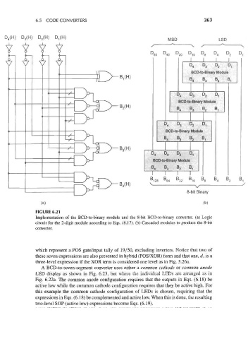
FIGURE 6.21
Implementation of the BCD-to-binary module and the 8-bit BCD-to-binary converter, (a) Logic
circuit for the 2-digit module according to Eqs. (6.17). (b) Cascaded modules to produce the 8-bit
converter.
which represent a POS gate/input tally of 19/50, excluding inverters. Notice that two of
these seven expressions are also presented in hybrid (POS/XOR) form and that one, d, is a
three-level expression if the XOR term is considered one level as in Fig. 3.26a.
A BCD-to-seven-segment converter uses either a common cathode or common anode
LED display as shown in Fig. 6.23, but where the individual LEDs are arranged as in
Fig. 6.22a. The common anode configuration requires that the outputs in Eqs. (6.18) be
active low while the common cathode configuration requires that they be active high. For
this example the common cathode configuration of LEDs is chosen, requiring that the
expressions in Eqs. (6.18) be complemented and active low. When this is done, the resulting
two-level SOP (active low) expressions become Eqs. (6.19),