
Page 295 - Engineering Digital Design
P. 295
266 CHAPTER 6 / NONARITHMETIC COMBINATIONAL LOGIC DEVICES
MSB LSB
BI(L) A(H) B(H) C(H) D(H)
g(L)
Bl : A B C D
Pecoder
a b c <J e f g
Y Y Y Y Y Y Y
(b)
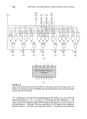
FIGURE 6.24
Logic circuit (a) and circuit symbol (b) for the BCD-to-seven-segment decoder according to Eqs. (6.19)
and Fig. 6.22, featuring an active low blanking input BI implemented by using inverting three-state
drivers with active low controls.
(A < B) represent A less than B. For cascading purposes, the inputs gt, eq, and It to the &th
stage are the outputs (A > B, A = B, and A < B) from the next least significant (k — l)th
stage, while the corresponding outputs of the kth stage are the inputs (gt, eq, and It) to the next
most significant (k + l)th stage. Thus, the magnitudes of the kth stage are more significant
than those of the (k — 1 )th stage, as the magnitudes of the (k -f 1 )th stage are more significant