
Page 294 - Engineering Digital Design
P. 294
6.6 MAGNITUDE COMPARATORS 265
Supply
a b c d e f g
(b)
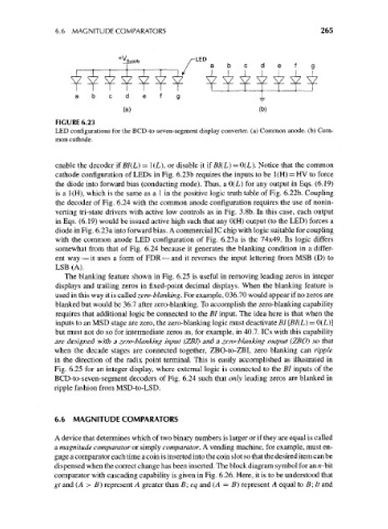
FIGURE 6.23
LED configurations for the BCD-to-seven-segment display converter, (a) Common anode, (b) Com-
mon cathode.
enable the decoder if BI(L) = 1(L), or disable it if BI(L) = 0(L). Notice that the common
cathode configuration of LEDs in Fig. 6.23b requires the inputs to be 1(H) = HV to force
the diode into forward bias (conducting mode). Thus, a 0(L) for any output in Eqs. (6.19)
is a 1(H), which is the same as a 1 in the positive logic truth table of Fig. 6.22b. Coupling
the decoder of Fig. 6.24 with the common anode configuration requires the use of nonin-
verting tri-state drivers with active low controls as in Fig. 3.8b. In this case, each output
in Eqs. (6.19) would be issued active high such that any 0(H) output (to the LED) forces a
diode in Fig. 6.23a into forward bias. A commercial 1C chip with logic suitable for coupling
with the common anode LED configuration of Fig. 6.23a is the 74x49. Its logic differs
somewhat from that of Fig. 6.24 because it generates the blanking condition in a differ-
ent way — it uses a form of FDR — and it reverses the input lettering from MSB (D) to
LSB (A).
The blanking feature shown in Fig. 6.25 is useful in removing leading zeros in integer
displays and trailing zeros in fixed-point decimal displays. When the blanking feature is
used in this way it is called zero-blanking. For example, 036.70 would appear if no zeros are
blanked but would be 36.7 after zero-blanking. To accomplish the zero-blanking capability
requires that additional logic be connected to the BI input. The idea here is that when the
inputs to an MSD stage are zero, the zero-blanking logic must deactivate BI [BI(L) = 0(L)]
but must not do so for intermediate zeros as, for example, in 40.7. ICs with this capability
are designed with a zero-blanking input (ZBI) and a zero-blanking output (ZBO) so that
when the decade stages are connected together, ZBO-to-ZBI, zero blanking can ripple
in the direction of the radix point terminal. This is easily accomplished as illustrated in
Fig. 6.25 for an integer display, where external logic is connected to the BI inputs of the
BCD-to-seven-segment decoders of Fig. 6.24 such that only leading zeros are blanked in
ripple fashion from MSD-to-LSD.
6.6 MAGNITUDE COMPARATORS
A device that determines which of two binary numbers is larger or if they are equal is called
a magnitude comparator or simply comparator. A vending machine, for example, must en-
gage a comparator each time a coin is inserted into the coin slot so that the desired item can be
dispensed when the correct change has been inserted. The block diagram symbol for an n-bit
comparator with cascading capability is given in Fig. 6.26. Here, it is to be understood that
gt and (A > B) represent A greater than B; eq and (A = B) represent A equal to B; It and