
Page 296 - Engineering Digital Design
P. 296
6.6 MAGNITUDE COMPARATORS 267
c(>— ZBO(H)
I I I I
BCD-tQ*Seven-Segment
Decoder [ ZBI
a b c d e f
a b Q d e f g TYYY Y Y Y
n rr nr T
(a) (b)
I I I I I I I
A B C D A B C D
_ g Q p I I A
0(H) ZBI (MSD) ZBO ZBI ZBO — ZBi (LSD)
a b c d e f g a b c d e f < a b c d e f
Y Y T T Y Y Y Y Y Y Y Y Y Y ^fYYYYY Y
(c)
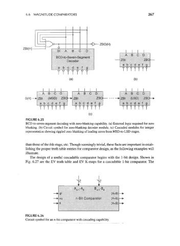
FIGURE 6.25
BCD-to-seven-segment decoding with zero-blanking capability, (a) External logic required for zero
blanking, (b) Circuit symbol for zero-blanking decoder module, (c) Cascaded modules for integer
representation showing rippled zero blanking of leading zeros from MSD-to-LSD stages.
than those of the fcth stage, etc. Though seemingly trivial, these facts are important in estab-
lishing the proper truth table entries for comparator design, as the following examples will
illustrate.
The design of a useful cascadable comparator begins with the 1-bit design. Shown in
Fig. 6.27 are the EV truth table and EV K-maps for a cascadable 1-bit comparator. The
(A>B)
ivBit Comparator (A=B)
(A<8)
FIGURE 6.26
Circuit symbol for an n-bit comparator with cascading capability.