
Page 361 - Engineering Electromagnetics, 8th Edition
P. 361
CHAPTER 10 Transmission Lines 343
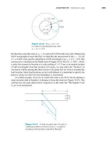
Figure 10.16 If z in = 2.5 + j 0
on a line 0.3 wavelengths long, then
z L = 2.1 + j 0.8.
We therefore enter the chart at z in = 2.5 and read 0.250 on the wtg scale. Subtracting
0.030 wavelength to reach the load, we find that the intersection of the s = 2.5 (or
| |= 0.429) circle and the radial line to 0.220 wavelength is at z L = 2.1+ j0.8. The
construction is sketched on the Smith chart of Figure 10.16. Thus Z L = 105+ j40 ,
avalue that assumes its location at a scale reading of −11.5 cm, or an integral number
of half-wavelengths from that position. Of course, we may select the “location” of
our load at will by placing the short circuit at the point that we wish to consider the
load location. Since load locations are not well defined, it is important to specify the
point (or plane) at which the load impedance is determined.
As a final example, let us try to match this load to the 50 line by placing a
short-circuited stub of length d 1 a distance d from the load (see Figure 10.17). The
stub line has the same characteristic impedance as the main line. The lengths d and
d 1 are to be determined.
Figure 10.17 A short-circuited stub of length d 1 ,
located at a distance d from a load Z L ,is used to
provide a matched load to the left of the stub.