
Page 366 - Engineering Electromagnetics, 8th Edition
P. 366
348 ENGINEERING ELECTROMAGNETICS
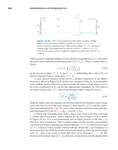
Figure 10.20 With series resistance at the battery location, voltage
division occurs when the switch is closed, such that V 0 = V rg + V .
+
1
Shown is the first reflected wave, which leaves voltage V + V 1 − behind its
+
1
leading edge. Associated with the wave is current I , which is −V /Z 0 .
−
−
1
1
Counterclockwise current is treated as negative and will occur when V 1 − is
positive.
Allowing time to approach infinity, the second term in parentheses in (117) becomes
the power series expansion for the expression 1/(1 − g L ). Thus, in steady state we
obtain
V L = V 1 + 1 + L (118)
1 − g L
In our present example, V 1 + = V 0 and g =−1. Substituting these into (118), we
find the expected result in steady state: V L = V 0 .
A more general situation would involve a nonzero impedance at the battery
location, as shown in Figure 10.20. In this case, a resistor of value R g is positioned in
series with the battery. When the switch is closed, the battery voltage appears across
the series combination of R g and the line characteristic impedance, Z 0 . The value of
the initial voltage wave, V ,is thus found through simple voltage division, or
+
1
V 1 + = V 0 Z 0 (119)
R g + Z 0
With this initial value, the sequence of reflections and the development of the voltage
across the load occurs in the same manner as determined by (117), with the steady-
state value determined by (118). The value of the reflection coefficient at the generator
end, determined by (116), is g = (R g − Z 0 )/(R g + Z 0 ).
A useful way of keeping track of the voltage at any point in the line is through
a voltage reflection diagram. Such a diagram for the line of Figure 10.20 is shown
in Figure 10.21a.Itisa two-dimensional plot in which position on the line, z,is
shown on the horizontal axis. Time is plotted on the vertical axis and is conveniently
expressed as it relates to position and velocity through t = z/ν.Avertical line, located
at z = l,is drawn, which, together with the ordinate, defines the z axis boundaries of
the transmission line. With the switch located at the battery position, the initial voltage
wave, V , starts at the origin, or lower-left corner of the diagram (z = t = 0). The
+
1
location of the leading edge of V as a function of time is shown as the diagonal line
+
1