
Page 364 - Engineering Electromagnetics, 8th Edition
P. 364
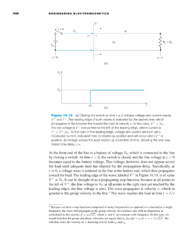
346                ENGINEERING ELECTROMAGNETICS


                                      Figure 10.19 (a) Closing the switch at time t = 0 initiates voltage and current waves
                                      V  +  and I . The leading edge of both waves is indicated by the dashed line, which
                                             +
                                      propagates in the lossless line toward the load at velocity ν.In this case, V  +  = V 0 ;
                                      the line voltage is V  +  everywhere to the left of the leading edge, where current is
                                      I  +  = V /Z 0 .To the right of the leading edge, voltage and current are both zero.
                                            +
                                      Clockwise current, indicated here, is treated as positive and will occur when V  +  is
                                      positive. (b)Voltage across the load resistor as a function of time, showing the one-way
                                      transit time delay, l /ν.

                                     At the front end of the line is a battery of voltage V 0 , which is connected to the line
                                     by closing a switch. At time t = 0, the switch is closed, and the line voltage at z = 0
                                     becomes equal to the battery voltage. This voltage, however, does not appear across
                                     the load until adequate time has elapsed for the propagation delay. Specifically, at
                                     t = 0, a voltage wave is initiated in the line at the battery end, which then propagates
                                     toward the load. The leading edge of the wave, labeled V in Figure 10.19, is of value
                                                                                 +
                                     V  +  = V 0 .It can be thought of as a propagating step function, because at all points to
                                     the left of V , the line voltage is V 0 ;at all points to the right (not yet reached by the
                                               +
                                     leading edge), the line voltage is zero. The wave propagates at velocity ν, which in
                                                                     4
                                     general is the group velocity in the line. The wave reaches the load at time t = l/ν


                                     4  Because we have a step function (composed of many frequencies) as opposed to a sinusoid at a single
                                     frequency, the wave will propagate at the group velocity. In a lossless line with no dispersion as
                                                          √
                                     considered in this section, β = ω LC, where L and C are constant with frequency. In this case, we
                                                                                              √
                                     would find that the group and phase velocities are equal; that is, dω/dβ = ω/β = ν = 1/ LC.We
                                     will thus write the velocity as ν, knowing it to be both ν p and ν g .