
Page 362 - Engineering Electromagnetics, 8th Edition
P. 362
344 ENGINEERING ELECTROMAGNETICS
The input impedance to the stub is a pure reactance; when combined in parallel
with the input impedance of the length d containing the load, the resultant input
impedance must be 1 + j0. Because it is much easier to combine admittances in
parallel than impedances, let us rephrase our goal in admittance language: the input
admittance of the length d containing the load must be 1 + jb in for the addition of
the input admittance of the stub jb stub to produce a total admittance of 1 + j0. Hence
the stub admittance is − jb in .We will therefore use the Smith chart as an admittance
chart instead of an impedance chart.
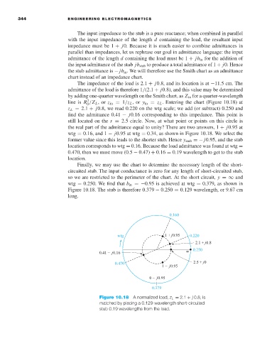
The impedance of the load is 2.1 + j0.8, and its location is at −11.5 cm. The
admittance of the load is therefore 1/(2.1 + j0.8), and this value may be determined
by adding one-quarter wavelength on the Smith chart, as Z in for a quarter-wavelength
2
line is R /Z L ,or z in = 1/z L ,or y in = z L . Entering the chart (Figure 10.18) at
0
z L = 2.1 + j0.8, we read 0.220 on the wtg scale; we add (or subtract) 0.250 and
find the admittance 0.41 − j0.16 corresponding to this impedance. This point is
still located on the s = 2.5 circle. Now, at what point or points on this circle is
the real part of the admittance equal to unity? There are two answers, 1 + j0.95 at
wtg = 0.16, and 1 − j0.95 at wtg = 0.34, as shown in Figure 10.18. We select the
former value since this leads to the shorter stub. Hence y stub =− j0.95, and the stub
location corresponds to wtg = 0.16. Because the load admittance was found at wtg =
0.470, then we must move (0.5 − 0.47) + 0.16 = 0.19 wavelength to get to the stub
location.
Finally, we may use the chart to determine the necessary length of the short-
circuited stub. The input conductance is zero for any length of short-circuited stub,
so we are restricted to the perimeter of the chart. At the short circuit, y =∞ and
wtg = 0.250. We find that b in =−0.95 is achieved at wtg = 0.379, as shown in
Figure 10.18. The stub is therefore 0.379 − 0.250 = 0.129 wavelength, or 9.67 cm
long.
Figure 10.18 A normalized load, z L = 2.1 + j 0.8, is
matched by placing a 0.129-wavelength short-circuited
stub 0.19 wavelengths from the load.