
Page 369 - Engineering Electromagnetics, 8th Edition
P. 369
CHAPTER 10 Transmission Lines 351
(a)
(b)
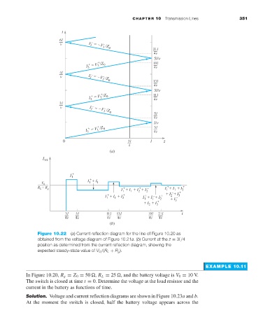
Figure 10.22 (a) Current reflection diagram for the line of Figure 10.20 as
obtained from the voltage diagram of Figure 10.21a.(b) Current at the z = 3l /4
position as determined from the current reflection diagram, showing the
expected steady-state value of V 0 /(R L + R g ).
EXAMPLE 10.11
In Figure 10.20, R g = Z 0 = 50 , R L = 25 , and the battery voltage is V 0 = 10 V.
The switch is closed at time t = 0. Determine the voltage at the load resistor and the
current in the battery as functions of time.
Solution. Voltage and current reflection diagrams are shown in Figure 10.23a and b.
At the moment the switch is closed, half the battery voltage appears across the