
Page 372 - Engineering Electromagnetics, 8th Edition
P. 372
354 ENGINEERING ELECTROMAGNETICS
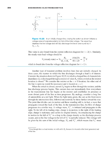
Figure 10.25 In an initially charged line, closing the switch as shown initiates a
voltage wave of opposite polarity to that of the initial voltage. The wave thus
depletes the line voltage and will fully discharge the line in one round trip if
R g = Z 0 .
This value is also found from the current reflection diagram for t > 2l/ν. Similarly,
the steady-state load voltage should be
R L (10)(25) 10
V L (steady state) = V 0 = = V
R g + R L 50 + 25 3
which is found also from the voltage reflection diagram for t > l/ν.
Another type of transient problem involves lines that are initially charged.In
these cases, the manner in which the line discharges through a load is of interest.
Consider the situation shown in Figure 10.25, in which a charged line of characteristic
impedance Z 0 is discharged through a resistor of value R g when a switch at the resistor
5
location is closed. We consider the resistor at the z = 0 location; the other end of
the line is open (as would be necessary) and is located at z = l.
When the switch is closed, current I R begins to flow through the resistor, and the
line discharge process begins. This current does not immediately flow everywhere
in the transmission line but begins at the resistor and establishes its presence at
more distant parts of the line as time progresses. By analogy, consider a long line
of automobiles at a red light. When the light turns green, the cars at the front move
through the intersection first, followed successively by those further toward the rear.
The point that divides cars in motion and those standing still is, in fact, a wave that
propagates toward the back of the line. In the transmission line, the flow of charge
progresses in a similar way. A voltage wave, V ,is initiated and propagates to the
+
1
right. To the left of its leading edge, charge is in motion; to the right of the leading
edge, charge is stationary and carries its original density. Accompanying the charge
in motion to the left of V 1 + is a drop in the charge density as the discharge process
occurs, and so the line voltage to the left of V is partially reduced. This voltage will
+
1
be given by the sum of the initial voltage, V 0 , and V , which means that V 1 + must
+
1
5 Even though this is a load resistor, we will call it R g because it is located at the front (generator) end
of the line.