
Page 370 - Engineering Electromagnetics, 8th Edition
P. 370
352 ENGINEERING ELECTROMAGNETICS
V
V
(a)
A
A
(b)
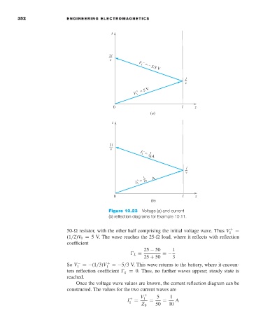
Figure 10.23 Voltage (a) and current
(b)reflection diagrams for Example 10.11.
50- resistor, with the other half comprising the initial voltage wave. Thus V 1 + =
(1/2)V 0 = 5V. The wave reaches the 25- load, where it reflects with reflection
coefficient
25 − 50 1
L = =−
25 + 50 3
So V 1 − =−(1/3)V 1 + =−5/3V. This wave returns to the battery, where it encoun-
ters reflection coefficient g = 0. Thus, no further waves appear; steady state is
reached.
Once the voltage wave values are known, the current reflection diagram can be
constructed. The values for the two current waves are
V + 5 1
I 1 + = 1 = = A
Z 0 50 10