Page 371 - Engineering Electromagnetics, 8th Edition
P. 371

CHAPTER 10   Transmission Lines           353

                     and
                                             V  −       5      1     1
                                       I  −  =−  1  =− −        =    A
                                       1
                                              Z 0       3   50     30
                     Note that no attempt is made here to derive I 1 −  from I . They are both obtained
                                                                   +
                                                                  1
                     independently from their respective voltages.
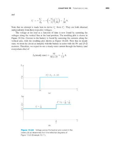
                         The voltage at the load as a function of time is now found by summing the
                     voltages along the vertical line at the load position. The resulting plot is shown in
                     Figure 10.24a. Current in the battery is found by summing the currents along the
                     vertical axis, with the resulting plot shown as Figure 10.24b. Note that in steady
                     state, we treat the circuit as lumped, with the battery in series with the 50- and 25-
                     resistors. Therefore, we expect to see a steady-state current through the battery (and
                     everywhere else) of
                                                         10       1
                                        I B (steady state) =  =     A
                                                       50 + 25   7.5


                                                      (a)


                                                      (b)
                             Figure 10.24 Voltage across the load (a) and current in the
                             battery (b)as determined from the reflection diagrams of
                             Figure 10.23 (Example 10.11).
   366   367   368   369   370   371   372   373   374   375   376