
Page 298 - Subyek Computer Aided Design - [David Planchard] Engineering Design with SOLIDWORKS
P. 298
Fundamentals of Drawing Engineering Design with SOLIDWORKS® 2018
GUIDE Part - Modify
A drawing contains part views, geometric dimensioning and tolerances, centerlines,
center marks, notes, custom properties and other related information. Perform the
following tasks before starting the GUIDE drawing:
• Verify the part. The drawing requires the associated part.
• View dimensions in each part. Step through each feature of the part and review all
dimensions.
• Review the dimension scheme to determine the required dimensions and notes to
manufacture the part.
I Activity: GUIDE Part - Modify
Open the GUIDE part.
116) Click Open e; from the Menu bar.
~ SweP, Open (Ctrl+O) ij Wra
117) Select the folder that the GUIDE document is in. Opens an existing document.
Modify the dimensions. References ...
118) Select the Filter Parts (*prt; *sldprt) button.
Quick Filter: ~ J ~II~ 11 f~ I
Part (*.prt;*.sldprt ~
119) Double-click GUIDE. v
Tl •
I Open Cancel J
120) Click Hidden Lines Visible ® from the Heads-up View
toolbar.
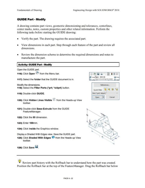
121) Double-click Base-Extrude from the GUIDE
FeatureManager.
122) Click the 80 dimension.
123) Enter 100mm.
124) Click inside the Graphics window.
Display a Shaded With Edges view. Save the GUIDE part.
125) Click Shaded With Edges ijJ from the Heads-up View
tool bar.
126) Click Save ~ .
' I /
;Q~ Review part history with the Rollback bar to understand how the part was created.
Position the Rollback bar at the top of the F eatureManager. Drag the Rollback bar below
PAGE4 - 22