
Page 303 - Subyek Computer Aided Design - [David Planchard] Engineering Design with SOLIDWORKS
P. 303
Engineering Design with SOLIDWORKS® 2018 Fundamentals of Drawing
The mouse pointer displays the Drawing View ~D icon when ce1 Select Other
the View properties and commands are executed. Selection Tools
Zoom/Pan/Rotate
Recent Commands
' I /
-;(J~ View the mouse pointer for feedback to select Sheet, Sheet (Sheet1)
§i Display Grid
View, and Component and Edge properties in the Drawing.
~ Edit Sheet Format
Lock Sheet Focus
Sheet Properties Add Sheet ..
~ Copy
• Sheet Properties display properties of the selected sheet. X Delete
Id I Properties ...
Right-click in the sheet boundary ~o to view the available
Relations/Snaps Options ...
commands. Comment
(' Smart Dimension
View Properties More Dimensions
An notations
• View Properties display properties of the selected view . Drawing Views
Tables
Right-click inside the ~D view boundary. Modify the View 9 Change Layer
Properties in the Display Style box or the View Toolbar. Customize Menu
Component Properties
~ 5elect Other
Selection Tools •
• Component Properties display properties of the selected
Zoom/Pan/Rotate
component. Right-click on the face of the component ~~ Becent Commands •
View (Drawing View1)
View the available options.
Lock View Position
Loi;k View Focus
Edge Properties Alignment
Reset sketch visibility
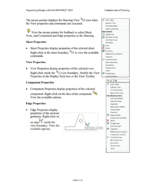
• Edge Properties display Tangent Edge •
properties of the selected Comment '
Replace Model
geometry. Right-click on
rs.: .. Conllert View to Sketch
Delete
an edgef ~ inside the
Change Layer
view boundary. View the ,-->--ij+ ____ --, Add View Label
Base Extrude of GUIDE
available options. Im Properties ...
RelationsLSnaps Options ...
Component Line font...
(' Smart Dimension
More Dimensions •
Annotations
Drawing Views •
Tables •
PAGE 4-27