
Page 306 - Subyek Computer Aided Design - [David Planchard] Engineering Design with SOLIDWORKS
P. 306
Fundamentals of Drawing Engineering Design with SOLIDWORKS® 2018
Detail View:
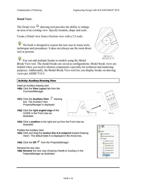
The Detail view G drawing tool provides the ability to enlarge
an area of an existing view. Specify location, shape and scale.
Create a Detail view from a Section view with a 3:2 scale.
+
' I /
-;Q~ The book is designed to expose the new user to many tools,
techniques and procedures. It does not always use the most direct
tool or process.
DETAIL c
' I /
-Q- SCALE 3 : 2
/ ' You can add multiple breaks to models using the Model
Break View tool. The model breaks are saved as configurations. Model break views are
helpful when you need to shorten components especially for technical and marketing
purposes. Additionally, the Model Break View tool lets you display breaks on drawing
views per ASME Y14.3.
I Activity: Auxiliary Drawing View
Insert an Auxiliary drawing view.
150) Click the View Layout tab from the
.
Command Manager.
A ~ '.'
' .
\
.
"
: '
.
. '
151) Click the Auxiliary View o~ drawing ' I
'
tool. The Auxiliary View
PropertyManager is displayed. -- ' ' '
'
~ --
~
'
I '
152) Click the right angled edge of the ; A~
GUIDE in the Front view as ' ' VIEW A·A
'
'
' '
'
'
illustrated.
153) Click a position to the right and up from the Front view as
illustrated.
Position the Auxiliary View.
!:§:~ GUIDE
154) Click and drag the section line A-A midpoint toward Drawing IA) Annotations
View1. The default label A is displayed in the Arrow box. '9]S eDrawings Markups
• 0 sheet1
• GJ Sheet Format1
155) Click the OK ~ from the PropertyManager.
• I~) Drawing View1
• G, GUIDE<28>
Rename the new view. • OJ Drawing View2
0
156) Rename the new view (Drawing View#) to Auxiliary in the • ~ Drawing View3
FeatureManager as illustrated. • ~ Drawing View4
• Ci~ AL!,Xiliary
1,, ~
PAGE4-30