
Page 310 - Subyek Computer Aided Design - [David Planchard] Engineering Design with SOLIDWORKS
P. 310
Fundamentals of Drawing Engineering Design with SOLIDWORKS® 2018
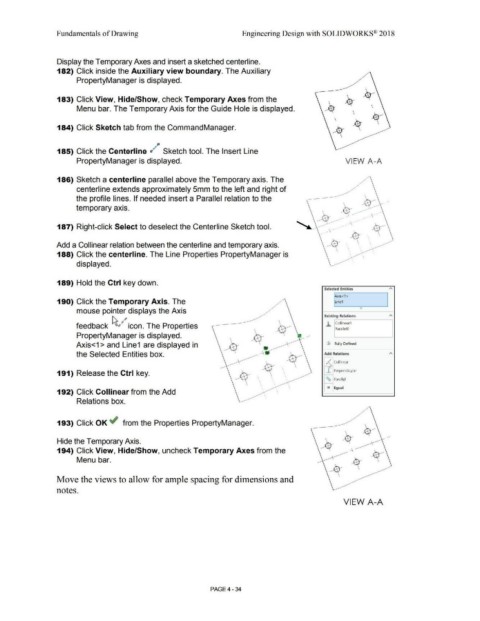
Display the Temporary Axes and insert a sketched centerline.
182) Click inside the Auxiliary view boundary. The Auxiliary
PropertyManager is displayed.
183) Click View, Hide/Show, check Temporary Axes from the
Menu bar. The Temporary Axis for the Guide Hole is displayed.
184) Click Sketch tab from the CommandManager.
#JJ
185) Click the Centerline d # Sketch tool. The Insert Line
PropertyManager is displayed. VIEW A-A
186) Sketch a centerline parallel above the Temporary axis. The
centerline extends approximately 5mm to the left and right of
the profile lines. If needed insert a Parallel relation to the
temporary axis. ~
' ------- ~
187) Right-click Select to deselect the Centerline Sketch tool. - -,- --- -_.-\-----· -\
Add a Collinear relation between the centerline and temporary axis. ' . ' ..
' ' .
188) Click the centerline. The Line Properties PropertyManager is ' .
'
displayed.
189) Hold the Ctrl key down.
Selected Entities
"'
1~xis<l >
190) Click the Temporary Axis. The Line1 I
mouse pointer displays the Axis "
Existing Relations
"'
feedback ~ ,-~-' icon. The Properties .h Collinearl
ParallelO
PropertyManager is displayed.
Axis<1 > and Line1 are displayed in (j) Fully Defined
the Selected Entities box. Add Relations "'
'1( Collinear
1 Perpendicu.lar
191) Release the Ctrl key.
~
\
Parallel
'
\ \ - Equal
-
192) Click Collinear from the Add ' \ '
'
Relations box.
193) Click OK ~ from the Properties PropertyManager.
Hide the Temporary Axis.
194) Click View, Hide/Show, uncheck Temporary Axes from the
Menu bar.
Move the views to allow for ample spacing for dimensions and
notes.
VIEW A-A
PAGE4 - 34