
Page 314 - Subyek Computer Aided Design - [David Planchard] Engineering Design with SOLIDWORKS
P. 314
Fundamentals of Drawing Engineering Design with SOLIDWORKS® 2018
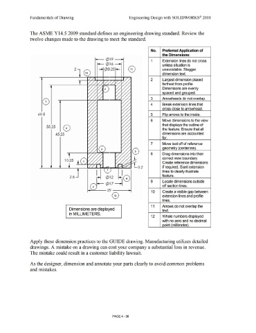
The ASME Y14.5 2009 standard defines an engineering drawing standard. Review the
twelve changes made to the drawing to meet the standard.
No. Preferred Application of
the Dimensions:
i.--- (pl 9 -a-i
1 Extension lines do not cross
.----- 0 1 6 --a-i unless situation is
'
2 -i (p8 .25 i--- unavoidable. Stagger
dimension text.
2 Largest dimension placed
farthest from profile.
Dimensions are evenly
spaced and qrouoed.
3 Arrowheads do not overlao.
0 4 Break extension lines that
cross close to arrowhead.
60.5 5 Flio arrows to the inside.
6 Move dimensions to the view
that displays the outline of
55.25
the feature. Ensure that all
45.25 dimensions are accounted
for.
7 Move text off of reference
aeometrv centerline •
8 Drag dimensions into their
correct view boundary.
10.25
Create reference dimensions
0.2 if required. Slant extension
I 7 I lines to clearly illustrate
2.5 feature.
9 Locate dimensions outside
0 17
s ' off section lines.
29 10 Create a visible gap between
0 extension lines and profile
lines.
11 Arrows do not overlap the
Dimensions are displayed text.
in MILLIMETERS.
12 Whole numbers displayed
with no zero and no decimal
ooint 'millimeter .
Apply these dimension practices to the GUIDE drawing. Manufacturing utilizes detailed
drawings. A mistake on a drawing can cost your company a substantial loss in revenue.
The mistake could result in a customer liability lawsuit.
As the designer, dimension and annotate your parts clearly to avoid common problems
and mistakes.
PAGE4 - 38