
Page 316 - Subyek Computer Aided Design - [David Planchard] Engineering Design with SOLIDWORKS
P. 316
Fundamentals of Drawing Engineering Design with SOLIDWORKS® 2018
Drawing dimension location is dependent on: ~ l~ I
~ Model Items G)
• Feature dimension creation. .., x
I
• Selected drawing views. Message v ""
Source/Destination A.
Source:
Note: The Import items into all views option, first inserts
Entire model v1
dimensions into Section Views and Detail Views. The
G2 Import items into all
remaining dimensions are distributed among the visible "fviews
views on the drawing. ...Qi- Place annotations into all views
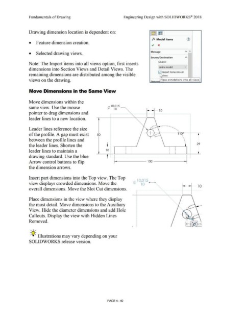
Move Dimensions in the Same View
Move dimensions within the
same view. Use the mouse rA 10.015
10 ----...
Y-J
pointer to drag dimensions and
'
leader lines to a new location.
Leader lines reference the size +
,~~ ~~~-----'1-'rA(r-~c.__--,-
of the profile. A gap must exist 50 ...__. &
between the profile lines and
the leader lines. Shorten the 29
leader lines to maintain a 10
drawing standard. Use the blue .................................................................................................................................... ~
Arrow control buttons to flip
the dimension arrows.
Insert part dimensions into the Top view. The Top
r/\ 10.015
view displays crowded dimensions. Move the VJ 10 41- , 1>,
i------+-- 1 0
overall dimensions. Move the Slot Cut dimensions.
r•••••••••••••••••••••••••••••••••• ••••••••••••••••••••••••• •·••••••••• •••••••••••••
•
•
•
•
•
•
•
•
•
Place dimensions in the view where they display •
•
•
•
•
•
•
the most detail. Move dimensions to the Auxiliary •
•
•
•
•
•
•
View. Hide the diameter dimensions and add Hole •
•
•
•
•
•
•
•
Callouts. Display the view with Hidden Lines •
•
•
•
•
•
Removed. •
•
•
•
•
• 01 "fJ. ch
•
•
•
I • '--1 It ii I-
, ,/
-;Q;. Illustrations may vary depending on your
SOLIDWORKS release version.
PAGE4 - 40