
Page 320 - Subyek Computer Aided Design - [David Planchard] Engineering Design with SOLIDWORKS
P. 320
Fundamentals of Drawing Engineering Design with SOLIDWORKS® 2018
Hide the following dimensions.
224) Right-click 25.
225) Click Hide. Right-click 6. Click Hide.
226) Right-click M3x0.5. Click Hide. Note: if required, hide any other
dimensions or annotations. Do not hide the 12 dimension.
, ,/
-;Q~ To show a hidden dimension, click View, Hide/Show, VIEW A-A
Annotations from the Menu bar.
Annotation Link Errors
Annotation Link Variables
Add a dimension. [!] Decals
fflf Grid
227) Click Smart Dimension <' from the Annotation toolbar. The
Ji Sketch Relations
Dimension PropertyManager is displayed.
jA~ Ann~tions
228) Click Smart dimensioning in the Dimension Assist Tools box. Click Hidde Views
the center point of the bottom left hole. Click the center point
of the bottom right hole.
229) Click a position below the profile as illustrated.
230) Check OK ~ from the Dimension PropertyManager.
20
Save the drawing.
VIEW A-A
231) Click Save 1111 . View the results.
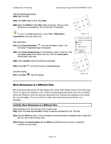
Move Dimensions to a Different View
Move the linear dimension 10 that defines the Linear Hole Pattern feature from Drawing
View3 (Top) to the Auxiliary view. When moving dimensions from one view to another,
utilize the Shift key and only drag the dimension text. Release the dimension text inside
the view boundary. The text will not switch views if positioned outside the view
boundary.
Activity: Move Dimensions to a Different View
Move dimensions from the Top view to the Auxiliary view.
232) Press the z key approximately 4 times to view the dimensions in the Top view.
233) Hold the Shift key down. Click and drag the vertical dimension 1 O between the 2 holes from
the Top view to the Auxiliary view.
234) Release the mouse button and the Shift key when the mouse pointer is inside the
Auxiliary view boundary.
PAGE4 - 44