
Page 325 - Subyek Computer Aided Design - [David Planchard] Engineering Design with SOLIDWORKS
P. 325
Engineering Design with SOLIDWORKS® 2018 Fundamentals of Drawing
257) Click inside the Detail view boundary. Centerlines are displayed.
258) Click inside the Section view boundary. Centerlines are 83 Centerline
displayed.
Message
To manually insert centerlines, select two
259) Click OK .; from the Centerline PropertyManager.
edges or sketch segments, or a single
cylindrical, conical, toroidal, or swept
face.
Save the drawing.
To automatically insert centerlines for
260) Click Save (ii. entire views, select the auto insert
option and then select one or more
drawing views.
Activate the Top view and insert Center marks. Auto Insert
~ elect View
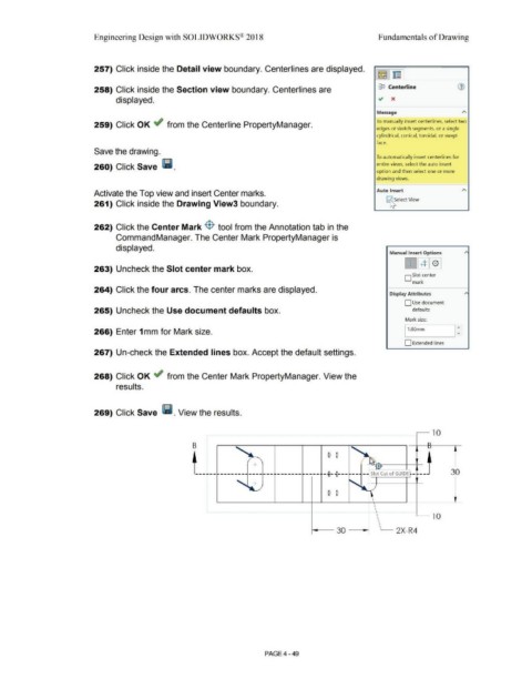
261) Click inside the Drawing View3 boundary.
262) Click the Center Mark $ tool from the Annotation tab in the
CommandManager. The Center Mark PropertyManager is
displayed.
Manual Insert Options
[IJGIJ[QJ
263) Uncheck the Slot center mark box.
D Slot center
mark
264) Click the four arcs. The center marks are displayed.
Display Attributes
D Use document
265) Uncheck the Use document defaults box. defaults
Mark size:
I:
266) Enter 1 mm for Mark size. 11.00mm
D Extended lines
267) Un-check the Extended lines box. Accept the default settings.
268) Click OK ~ from the Center Mark PropertyManager. View the
results.
269) Click Save l!I. View the results.
~ 10
B
0 0
+
Slot Cut of GUIDE - 30
0 0
,____ l O
,____ 2X-R4
i---- 30 - ---.!
PAGE4 - 49