
Page 328 - Subyek Computer Aided Design - [David Planchard] Engineering Design with SOLIDWORKS
P. 328
Fundamentals of Drawing Engineering Design with SOLIDWORKS® 2018
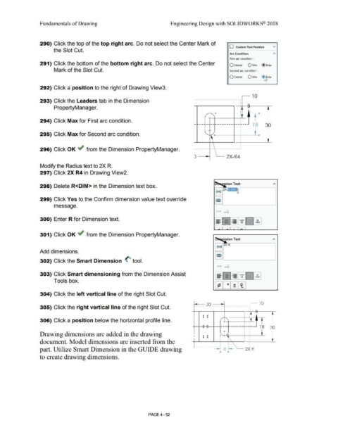
290) Click the top of the top right arc. Do not select the Center Mark of
D Custom Text Position v
the Slot Cut.
Arc Condition A
First arc condition :
291) Click the bottom of the bottom right arc. Do not select the Center O Center O Min @ Max
Mark of the Slot Cut. Second arc condition :
O Center O Min ~ax
292) Click a position to the right of Drawing View3.
.- 10
.
293) Click the Leaders tab in the Dimension ·-··········· ························· ······················
.
.
.
.
.
PropertyManager.
. ! D
.
.
+---1----+----'-''. -
.
.
294) Click Max for First arc condition. . I
.
- -- - ---------- ----- 18 30
.
.
.
.
.
.
.
.
.
.
.
.
295) Click Max for Second arc condition. '-1-f"' D---1------+-' -~-<I
.
.
.
.
.
296) Click OK -if from the Dimension PropertyManager.
) - --i ~ 2X-R4
Modify the Radius text to 2X R.
297) Click 2X R4 in Drawing View2.
298) Delete R<DIM> in the Dimension text box.
299) Click Yes to the Confirm dimension value text override
message.
• + ~
300) Enter R for Dimension text.
301) Click OK ~ from the Dimension PropertyManager.
· ension Text
Add dimensions.
302) Click the Smart Dimension <' tool.
• + .4
-
303) Click Smart dimensioning from the Dimension Assist - - - - •XX• .xx. xx
-
-
-
-
- -
-
-
-
- - - - xx xx •XX•
Tools box.
304) Click the left vertical line of the right Slot Cut.
30 10
. . . . . . . . . . ..... . . . . . . . . . ....... . ..... .. ...... ......... . .... . . .....
305) Click the right vertical line of the right Slot Cut.
~
~
0 0
306) Click a position below the horizontal profile line. / + '
-1--- ---0--0--- ---------------- 1------- 18 30
+
Drawing dimensions are added in the drawing I 0 0 • ,
'
document. Model dimensions are inserted from the . t\
\
..
part. Utilize Smart Dimension in the GUIDE drawing -- 8~ 2X R
-
• •
to create drawing dimensions.
PAGE4 - 52