
Page 323 - Subyek Computer Aided Design - [David Planchard] Engineering Design with SOLIDWORKS
P. 323
Engineering Design with SOLIDWORKS® 2018 Fundamentals of Drawing
, ,/
-;Q~ Know inch/mm decimal display. The ASME Y14.5-2009 standard states:
• For millimeter dimensions <l , display the leading zero. Remove trailing zeroes.
• For inch dimensions <1, delete the leading zero. The dimension is displayed with the
same number of decimal places as its tolerance.
Symbols are located on the bottom of the Dimension Text dialog box. The current text is
displayed in the text box. Example:
• <NUM INST>: Number of Instances in a Pattern.
• <MOD-DIAM>: Diameter symbol ¢.
• <HOLE-DEPTH>: Deep symbol ~.
• <HOLE-SPOT>: Counterbore symbol u.
• <DIM>: Dimension value 3. ,----------------------------- ------------- -----------------------
•
•
•
•
•
•
•
•
•
•
•
•
Fit the Drawing to the Graphics window. •
•
•
•
•
•
244) Press the f key. •
•
•
•
•
•
•
•
•
•
•
•
•
If needed, insert dimension text. • I I I I
•
•
•
• I I I I
I
I
I
•
I
245) Click inside the Drawing View1 boundary. The • I I I I
•
•
•
•
Drawing View1 PropertyManager is displayed. ~--·····-·······-····--·············-···············-·-····-········
i------100 ----
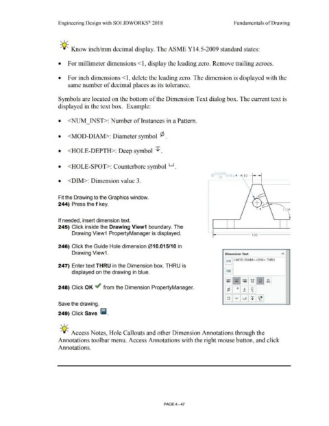
246) Click the Guide Hole dimension 010.015/1 O in
Drawing View1. Dimension Text
I (xx) I <MOD·DIAM><DIM> THRU
247) Enter text THRU in the Dimension box. THRU is
displayed on the drawing in blue.
248) Click OK ~ from the Dimension PropertyManager.
Save the drawing.
249) Click Save lf.i.
, ,/
-;Q~ Access Notes, Hole Callouts and other Dimension Annotations through the
Annotations toolbar menu. Access Annotations with the right mouse button, and click
Annotations.
PAGE4-47