
Page 318 - Subyek Computer Aided Design - [David Planchard] Engineering Design with SOLIDWORKS
P. 318
Fundamentals of Drawing Engineering Design with SOLIDWORKS® 2018
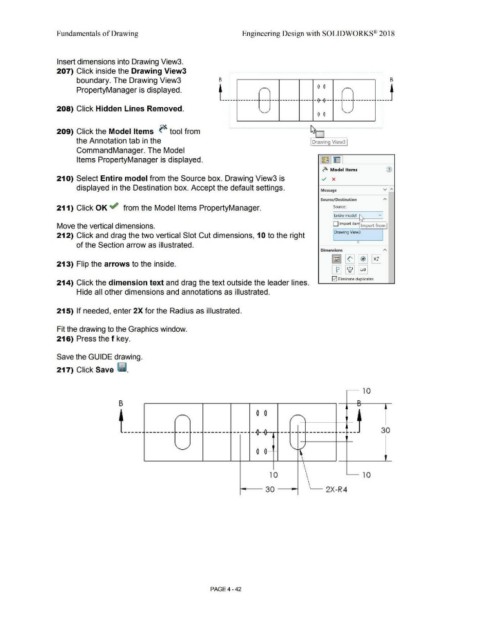
Insert dimensions into Drawing View3.
207) Click inside the Drawing View3 , ..............................•.•.••.••.•............•.•..••... ······················· ..... . . ....
• .
. •
•
•
boundary. The Drawing View3 B : 1 B
.
•
•
•
. 0 0 - .
•
•
•
•
PropertyManager is displayed. . r ' / ' .
•
•
•
. .
•
.
•
•
. .
•
•
•
•
---:-- . ------------ . --· ------- ----· --0---0--- i,.--· ------------ --~--
•
•
. .
•
•
•
208) Click Hidden Lines Removed. . ,
.
•
. ' '
•
.
•
• 0 0
•
•
··~ • ············· ....................................... :
.
•
•
•
: ................................................. ·············t
209) Click the Model Items ~ tool from
'
the Annotation tab in the Drawing View3
CommandManager. The Model
Items PropertyManager is displayed. l~ l~ I
~ Model Items (J)
21 O) Select Entire model from the Source box. Drawing View3 is ../ x
displayed in the Destination box. Accept the default settings. Message v ,...
Source/ Destination
211) Click OK ~ from the Model Items PropertyManager. Source:
I Entire model ~ v I
Move the vertical dimensions. D Import iten Import from
Drawing View3
212) Click and drag the two vertical Slot Cut dimensions, 1 O to the right
of the Section arrow as illustrated.
Dimensions
213) Flip the arrows to the inside.
E2I Eliminate duplicates
214) Click the dimension text and drag the text outside the leader lines.
Hide all other dimensions and annotations as illustrated.
215) If needed, enter 2X for the Radius as illustrated.
Fit the drawing to the Graphics window.
216) Press the f key.
Save the GUIDE drawing.
217) Click Save ii.
10
B n
L)
0 0
I' /
'
·--
-----. --------·--- ~--- -------· ·----· --0- ---------------· ---- 30
\..
0 0 •
10 10
30 2X-R4
PAGE4-42