
Page 313 - Subyek Computer Aided Design - [David Planchard] Engineering Design with SOLIDWORKS
P. 313
Engineering Design with SOLIDWORKS® 2018 Fundamentals of Drawing
Detail Drawing
The design intent of this project is to work with dimensions inserted from parts and to
incorporate them into the drawings. Explore methods to move, hide and recreate
dimensions to adhere to a drawing standard.
There are other solutions to the dimensioning schemes illustrated in this project. Detail
drawings require dimensions, annotations, tolerance, materials, Engineering Change
Orders, authorization, etc. to release the part to manufacturing and other notes prior to
production.
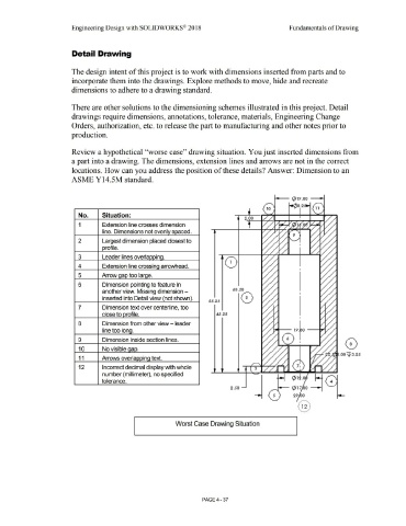
Review a hypothetical ''worse case'' drawing situation. You just inserted dimensions from
a part into a drawing. The dimensions, extension lines and arrows are not in the correct
locations. How can you address the position of these details? Answer: Dimension to an
ASME Y14.5M standard.
.,__ (}) 19 .00 --t
.---..
i,,.(l}8 . 2 $1,-1
1 1
No. Situation:
2.00
1 Extension line crosses dimension
line. Dimensions not evenly spaced.
2 Largest dimension placed closest to
profile.
3 Leader lines overla· .. ina.
1
4 Extension line crossina arrowhead.
5 Arrow aao too larae.
6 Dimension pointing to feature in
another view. Missing dimension - 60.50
inserted into Detail view not shown, . 0
SS .25
7 Dimension text over centerline, too
close to orofile. 45 .25
8 Dimension from other view - leader
line too Iona.
9 Dimension inside section lines. 0
10 No visible aao.
11 Arrows overla, .. 1ina text.
12 Incorrect decimal display with whole 3
number (millimeter), no specified
tolerance.
2 . .so _t-- (}) 1 7 0 -9"i
Worst Case Drawing Situation
PAGE4 -37