
Page 311 - Subyek Computer Aided Design - [David Planchard] Engineering Design with SOLIDWORKS
P. 311
Engineering Design with SOLIDWORKS® 2018 Fundamentals of Drawing
~ Additional information on creating a New Drawing, Model View, Move View,
Auxiliary View, Section View, and Detail View are located in the SOLIDWORKS Help
Topics section. Keywords: New ( drawing document), Auxiliary View, Detail View,
Section View and Crop View.
st"'·~~ ~
{:,.. Review the GUIDE Drawing
You created a new drawing, GUIDE with the B-ANSI-MM Drawing Template. The
GUIDE drawing utilized the GUIDE part in the Model View PropertyManager. The
Model View PropertyManager allowed new views to be inserted with a View
Orientation. You selected Front, Top, Right and Isometric to position the GUIDE views.
Additional views were required to fully detail the GUIDE. You inserted the Auxiliary
Section, Detail, Partial Auxiliary and Crop view. You moved the views by dragging the
view boundary. The next step is to insert the dimensions and annotations to detail the
GUIDE drawing.
Display Modes and Perfonnance
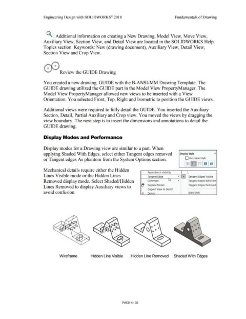
Display modes for a Drawing view are similar to a part. When
applying Shaded With Edges, select either Tangent edges removed Display Style
or Tangent edges As phantom from the System Options section. D Use parent style
Mechanical details require either the Hidden
Reset sketch visibility \
'
Lines Visible mode or the Hidden Lines Tangent Edge • 0 Tangent Edges Visible
•
Removed display mode. Select Shaded/Hidden Comment L.s • Tangent Edges With Font
~ ReQlace Model Tangent Edges Removed
Lines Removed to display Auxiliary views to
Convert View to Sketch
avoid confusion. x Delete Hide Ends
0
0
:\ 0 0
\.) 0 0
Wireframe Hidden Line Visible Hidden Line Removed Shaded With Edges
PAGE4 -35