
Page 315 - Subyek Computer Aided Design - [David Planchard] Engineering Design with SOLIDWORKS
P. 315
Engineering Design with SOLIDWORKS® 2018 Fundamentals of Drawing
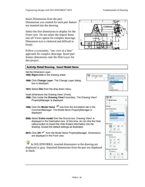
Insert Dimensions from the part.
I I I
Dimensions you created for each part feature
are inserted into the drawing.
Cluttered
Select the first dimensions to display for the
Front view. Do not select the Import Items
into all Views option for complex drawings.
Dimension text is cluttered and difficult to
locate.
Follow a systematic, ''one view at a time''
approach for complex drawings. Insert part
feature dimensions onto the Dim Layer for
this project.
Activity: Detail Drawing- Insert Model Items
Set the Dimension Layer.
195) Right-click in the drawing sheet.
Change document layer.
-None- ~
196) Click Change Layer. The Change Layer dialog -Per Standard-
box is displayed. FORMAT
Dim
Notes
197) Select Dim from the drop-down menu.
Hidden Dims
Insert dimensions into Drawing View1 (Front).
198) Click inside the Drawing View1 boundary. The Drawing View1 ~ IE
PropertyManager is displayed. ~ Model Items
v x
v ;,,
Message
199) Click the Model Items ~ tool from the Annotation tab in the
Source/Destination
CommandManager. The Model Items PropertyManager is
Source:
displayed.
Selected feature
200) Select Entire model from the Source box. Drawing View1 is raw1ng 1ew
displayed in the Destination box. At this time, do not click the Hole
callout button to import the Hole Wizard information into the Dimensions A
drawing. Accept the default settings as illustrated.
201) Click OK ~ from the Model Items PropertyManager. Dimensions 0 Eliminate duplicates
are displayed in the Front view. Annotations
Oselect all
, ,/
-;Q~ In SOLIDWORKS, inserted dimensions in the drawing are
displayed in gray. Imported dimensions from the part are displayed
Reference Geometry
in black. D Select all
PAGE4 - 39