
Page 319 - Subyek Computer Aided Design - [David Planchard] Engineering Design with SOLIDWORKS
P. 319
Engineering Design with SOLIDWORKS® 2018 Fundamentals of Drawing
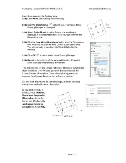
Insert dimensions into the Auxiliary View.
218) Click inside the Auxiliary view boundary.
··~
219) Click the Model Items ~ Drawing tool. The Model Items
PropertyManager is displayed. Auxiliary
.
.
.
.
.
.
.
•
•
220) Select Entire Model from the Source box. Auxiliary is .
.
•
•
.
•
displayed in the Destination box. View your options from the .
•
.
•
.
•
•
Dimensions box. .
.
•
•
221) Click the Hole Wizard Locations button from the Dimensions ~J~ l
box. Note: Do not click the Hole Callout button at this time.
~ Model Items G)
You will manually create the Hole Wizard Callout in the
v x
drawing.
v ,..
Message
Source/Destination A
222) Click OK ~ from the Model Items PropertyManager. Source:
f Entire model v
223) Move the dimensions off the view as illustrated. If needed D Import items into all views
zoom in on the dimensions to move them. I Auxiliary
I
(')
The dimensions for the Linear Pattern of Holes are determined Dimensions "'
~ [I] [*1 ~
•
from the initial Hole Wizard position dimensions and the
Linear Pattern dimensions. Your dimensioning standard CfJ -~ B
0 Elimin ~r · .. I
requires the distance between the holes in a pattern. Hole Wizard Locations
Do not over dimension. In the next steps, hide the existing
dimensions and add a new dimension. Trailing zeroes:
Dimensions: [Smart vi
In the next section, if
Tolerances: !Remove only on zero I
needed, click Options, Properties: Show J
25 1
Document Properties,
Dimensions from the O Show units of dimensions
Menu bar. Uncheck the ~ Add parentheses by default
Center between extension lines
Add parentheses by
\ O Include prefix inside basic tolerance box
default box. Click OK. n.· . ,.., ' .... 1 • . . ;...._ """-""' h .... v
12
~ 6
M3x0.5 ___,
VIEW A-A
PAGE4 - 43