Page 326 - Subyek Computer Aided Design - [David Planchard] Engineering Design with SOLIDWORKS
P. 326

Fundamentals of Drawing                                                                                                                                    Engineering Design with SOLIDWORKS® 2018


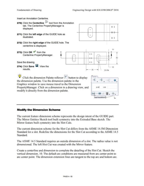
                                                Insert an Annotation Centerline.


                                                270) Click the Centerline  fp tool from the Annotation


                                                                tab. The Centerline PropertyManager is

                                                                                                                                                                                                                                                                                                          I            0  0
                                                                 displayed.                                                                                                                                                                           /'       '\
                                                                                                                                                                                                                                                          +


                                                                                                                                                                                                                             ---------                 ------- i,.------- --- --·  ,-~--{}---                                           ....


                                                271) Click the left edge of the GU I DE hole as
                                                                                                                                                                                                                                                          +

                                                                 illustrated.                                                                                                                                                                         \..
                                                                                                                                                                                                                                                                                                                       0  0


                                                272) Click the right edge of the GUIDE hole. The


                                                                 centerline is displayed.


                                                                                                                                                                                                                                                                                                                         IU
                                                                                                                                                                                                                                                                                                                      -
                                                273) Click OK ~ from the                                                                                                 s                                                                                                                                            ~


                                                                 Centerline PropertyManager.                                                                                                               /   -                                I         0  0                /   -  '                                 •
                                                                                                                                                                                                             +                                                                   +

                                                                                                                                                                                        --------·  ~---- ---              to----------- --            --e--e------ -- -· --------                        ,-- ~---                  30


                                                                                                                                                                                                             +


                                                Save the drawing.                                                                                                                                         ' -                                             0  0                '    1


                                                274) Click Save  lill. View the                                                                                                                                                                                                                                          10


                                                                 results.                                                                                                                                                                                       30                                 2X-R4


                                                   , ,/


                                                                                                                                                                                                                                                                   ,.~,,,,.,.,
                                                                                                                                                                                                                                                                   ,.,.,.,.,.,.,.
                                                  -;Q~ Click the dimension Palette rollover I(' I button to display
                                                                                                                                                                                                                                                                      •.01                1>1
                                                                                                                                                                                                                                                                   1.50                tXX.X
                                                the dimension palette. Use the dimension palette in the                                                                                                                                                               -.01    ...         .01    ...


                                                Graphics window to save mouse travel to the Dimension


                                                PropertyManager. Click on a dimension in a drawing view, and                                                                                                                                                                2X-~                3.00


                                                modify it directly from the dimension palette.


                                                                                                                                                                                                                                                                                                         -              .xx ..
                                                                                                                                                                                                                                                                                                         -
                                                                                                                                                                                                                                                                                                         - ...
                                                                                                                                                                                                                                                                                                                          xx  ...


                                                                                                                                                                                                                                                                       Add Parenthesis L-----


                                                Modify the Dimension Scheme


                                                The current feature dimension scheme represents the design intent of the GUIDE part.


                                                The Mirror Entities Sketch tool built symmetry into the Extruded Base sketch. The


                                                Mirror feature built symmetry into the Slot Cuts.


                                                The current dimension scheme for the Slot Cut differs from the ASME 14.5M Dimension


                                                Standard for a slot. Redefine the dimensions for the Slot Cut according to the ASME 14.5


                                                Standard.


                                                The ASME 14.5 Standard requires an outside dimension of a slot. The radius value is not


                                                dimensioned. The left Slot Cut was created with the Mirror feature.


                                                Create a centerline and dimension to complete the detailing of the Slot Cut. Sketch the


                                                vertical dimension, 10. The default arc conditions are measured from arc center point to


                                                arc center point. The dimension extension lines are tangent to the top arc and bottom arc.


                                                                                                                                                                                PAGE4 -50
   321   322   323   324   325   326   327   328   329   330   331