
Page 330 - Subyek Computer Aided Design - [David Planchard] Engineering Design with SOLIDWORKS
P. 330
Fundamentals of Drawing Engineering Design with SOLIDWORKS® 2018
, ,/
-;Q;:, Design parts to maximize symmetry and geometric relations to fully define sketches.
Minimize dimensions in the part. Insert dimensions in the drawing to adhere to
machining requirements and Dimension Standards.
Examples: Insert reference dimensions by adding parentheses and redefine a slot
dimension scheme according to the ASME Y14.5 standard.
~ Additional Information Dimensions and Annotations are found in SOLID WORKS
Help Topics. Keywords: Dimensions ( circles, extension lines, inserting into drawings,
move, parenthesis), Annotations (Hole Callout, Centerline and Center Mark).
~"""~$ <>
(:_:,,. . Review Dimensions and Annotations
You inserted part dimensions and annotations into the drawing. Dimensions were moved
to new positions. Leader lines and dimension text were repositioned. Annotations were
edited to reflect the drawing standard.
Centerlines and Center Marks were inserted into each view and were modified in the
PropertyManager. You modified Hole Callouts, dimensions, annotations and referenced
dimensions to conform to the drawing standard.
GUIDE Part - Insert an Additional Feature
The design process is dynamic. We do not live in a static world. Create and add an edge
Fillet feature to the GUIDE part. Insert dimensions into Drawing Viewl; (Front).
Activity: GUIDE Part - Insert an Additional Feature
Open the Guide part.
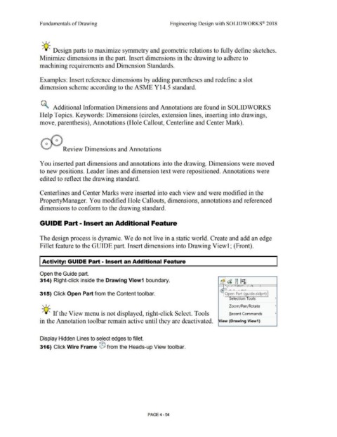
314) Right-click inside the Drawing View1 boundary. b~'a
~ I· I
~ J [j ®
' / / / I
- ~
'
LC
315) Click Open Part from the Content toolbar. Open Part (guide.sldprt)
Selection Tools •
, ,/
Zoom/Pan/Rotate •
-;Q;:, If the View menu is not displayed, right-click Select. Tools Recent Commands •
in the Annotation toolbar remain active until they are deactivated. iew (Drawing View1}
Display Hidden Lines to select edges to fillet.
316) Click Wire Frame ® from the Heads-up View toolbar.
PAGE4 - 54