
Page 332 - Subyek Computer Aided Design - [David Planchard] Engineering Design with SOLIDWORKS
P. 332
Fundamentals of Drawing Engineering Design with SOLIDWORKS® 2018
Insert dimensions into Drawing View1.
330) Click the Model Items ~ tool from the Annotation tab. The Model Items PropertyManager
is displayed. Accept the default conditions.
331) Click OK ~ from the Model Items PropertyManager. Note: Hide any unwanted annotation
or dimension in the Detail view.
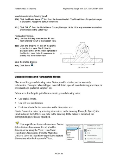
Position the Fillet text.
332) Use the Shift key to move the R1 text
from Drawing View1 to the Section view.
333) Click and drag the R1 text off the profile
in the Section view. The R1 text is
displayed either on the left or right side of
the Section view. Note: It may come in R 1 ---~
directly into the Section view.
Save the GUIDE drawing.
334) Click Save lill. 60
SECTION 8-8
General Notes and Parametric Notes
Plan ahead for general drawing notes. Notes provide relative part or assembly
information. Example: Material type, material finish, special manufacturing procedure or
considerations, preferred supplier, etc.
Below are a few helpful guidelines to create general drawing notes:
• Use capital letters.
• Use left text justification.
• Font size should be the same size as the dimension text.
Create Parametric notes by selecting dimensions in the drawing. Example: Specify the
Fillet radius of the GUIDE as a note in the drawing. If the radius is modified, the
corresponding note is also modified.
, ,/
-;Q~ Hide superfluous feature dimensions. Do not
Change document layer. Annotation l ink Errors
delete feature dimensions. Recall a hidden
Annotation l ink Variables
dimension by using the View, Hide/Show, ,,___[ ----~ Q l~I Decals
-Per Standard-
Hide/Show Annotations from the Menu bar. -None- fi Grid
Dims
Utilize a Layer to Hide/Show superfluous feature - Notes 4'> Sketch Relations
Hidden Dims
dimensions with the Layer on/off icon. A~ Hide/ Show Annotations
FORMAT
Hidden Views
PAGE4 - 56