
Page 305 - Subyek Computer Aided Design - [David Planchard] Engineering Design with SOLIDWORKS
P. 305
Engineering Design with SOLIDWORKS® 2018 Fundamentals of Drawing
' I /
-;(J~ Select the dashed view boundary to move
,------------------------------------------------------- •
•
a view in the drawing. •
•
•
•
•
•
•
•
:ts
•
•
·~---~
•
'---,--~~ •
•
•
. ' I : [ Drawing View1
' .
. ' ' • ' •
~~~---~~~ .
• •
----------------------------------------------~------·-'
Auxiliary View, Section View, and Detail View
The GUIDE drawing requires additional
OJ ~ OJ -~& ... a [3J [S)) ~ lli8
11 1
I
views to document the part. Insert an 0:8 0 o·· .....
Standard Model Projected Auxiliary Section Detail Broken-out Break Crop Alternate
Auxiliary view, Section view and Detail 3 View View View View View View Section View View Position View
view from the View Layout tab in the View Layout Annotation Sketch Evaluate SOLIDWORKS Add-Ins Sheet Format
CommandManager. Review the
following view terminology before you
begin the next activity.
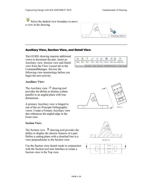
Auxiliary View:
The Auxiliary view ~ drawing tool A ,.,,,,-\
•
'
provides the ability to display a plane '
'
'
'
' \
parallel to an angled plane with true ' \ •
\
\
•
dimensions. ' •
'
'
'
' \
'
\
\
' \
A primary Auxiliary view is hinged to • '
'
•
'
'
one of the six Principle Orthographic ._____.__._ _____ ...........__~ A ~ ' VlE WA-A
views. Create a Primary Auxiliary view
that references the angled edge in the
Front view.
Section View:
The Section view ~ drawing tool provides the
ability to display the interior features of a part.
Define a cutting plane with a sketched line in a
view perpendicular to the Section view. SECTION B-B
B B
Use the Section view sketch mode in conjunction t ____ _ - 0 0 - _____ t
with the Section tool user interface to create a . --------~--- --· ------- ---- --o-~-- -- ------------
Section view in the Top view. - 0 0 '--"'
PAGE4 - 29