
Page 300 - Subyek Computer Aided Design - [David Planchard] Engineering Design with SOLIDWORKS
P. 300
FundamentaJs of Drawing Engineering Design with SOLIDWORKS" 2018
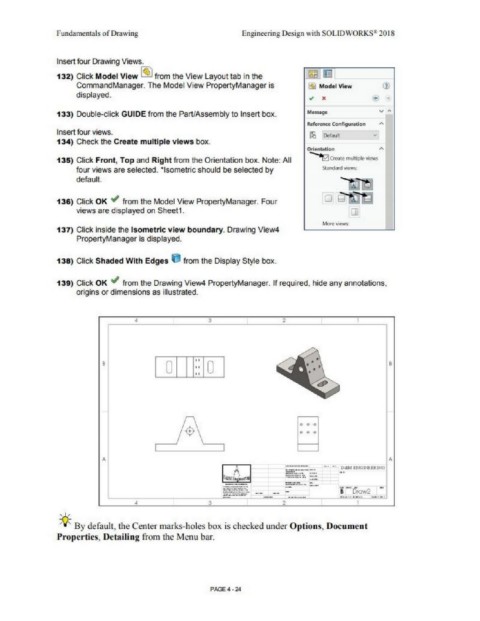
Insert four Drawing Views.
132) Click Model View @bl from the View Layout tab in the
CommandManager. The Model View PropertyManager is lj) Model View
displayed. ., x
133) Double-click GUIDE from the Part/Assembly to Insert box.
RC'fef'entt Configunition "
Insert four views.
134) Check the Create multiple views box.
Ot-1e-ntatlon "
135) Click Front, Top and Right from the Orientation box. Note: All ~ (l'(tlltt> m"ltipleviews
four views are selected. ·isometric should be selected by Smndiln:I <kws:
default.
136) Click OK ,I' from the Model View PropertyManager. Four
views are displayed on Sheet1. []
MQtOViCW$:
137) Click inside the Isometric view boundary. Drawing View4
PropertyManager is displayed.
138) Click Shaded With Edges 6 from the Display Styte box.
139) Click OK ~ from the Drawing View4 PropertyManager. If required, hide any annotations,
origins or dimensions as illustrated.
• 3 2
I o I 11:: Io I •
Fl
td
A A
.................
-··~···'" - ... ,,
...----·....--
=:-::= =-· ::.:
........ -· .......
2
, ,,
-JJ~ By default, the Center marks-holes box is checked 1mder Options, Document
Properties, Detailing from the Menu bar.
PAGE4·24