
Page 440 - Subyek Computer Aided Design - [David Planchard] Engineering Design with SOLIDWORKS
P. 440
Extrude and Revolve Features Engineering Design with SOLIDWORKS® 2018
Mold Base
Designing a custom mold base is expensive
and time consuming. An example of a mold
base supplier is Progressive Components ·-·
( www. procomps. com).
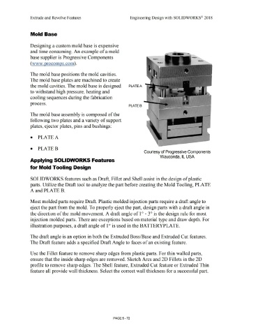
The mold base positions the mold cavities.
The mold base plates are machined to create
the mold cavities. The mold base is designed PLATE A
to withstand high pressure, heating and
cooling sequences during the fabrication I
process.
PLATE B
The mold base assembly is composed of the
following two plates and a variety of support
plates, ejector plates, pins and bushings:
• PLATEA
• PLATEB
Courtesy of Progressive Components
Wauconda, IL USA
Applying SOLIDWORKS Features
for Mold Tooling Design
SOLIDWORKS features such as Draft, Fillet and Shell assist in the design of plastic
parts. Utilize the Draft tool to analyze the part before creating the Mold Tooling, PLATE
A and PLATE B.
Most molded parts require Draft. Plastic molded injection parts require a draft angle to
eject the part from the mold. To properly eject the part, design parts with a draft angle in
the direction of the mold movement. A draft angle of 1 ° - 3 ° is the design rule for most
injection molded parts. There are exceptions based on material type and draw depth. For
illustration purposes, a draft angle of 1 ° is used in the BATTERYPLATE.
The draft angle is an option in both the Extruded Boss/Base and Extruded Cut features.
The Draft feature adds a specified Draft Angle to faces of an existing feature.
Use the Fillet feature to remove sharp edges from plastic parts. For thin walled parts,
ensure that the inside sharp edges are removed. Sketch Arcs and 2D Fillets in the 2D
profile to remove sharp edges. The Shell feature, Extruded Cut feature or Extruded Thin
feature all provide wall thickness. Select the correct wall thickness for a successful part.
PAGE 5- 72