
Page 444 - Subyek Computer Aided Design - [David Planchard] Engineering Design with SOLIDWORKS
P. 444
Extrude and Revolve Features Engineering Design with SOLIDWORKS® 2018
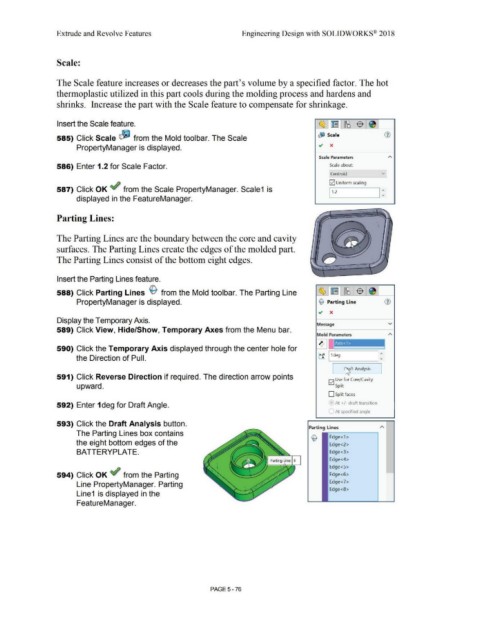
Scale:
The Scale feature increases or decreases the part's volume by a specified factor. The hot
thermoplastic utilized in this part cools during the molding process and hardens and
shrinks. Increase the part with the Scale feature to compensate for shrinkage.
Insert the Scale feature. ~l~ l~I~ ! I
&) Scale G)
585) Click Scale ~ from the Mold toolbar. The Scale
PropertyManager is displayed.
Scale Parameters
586) Enter 1.2 for Scale Factor. Scale about:
Centroid v]
G2] Uniform scaling
587) Click OK ef from the Scale PropertyManager. Scale1 is I :
1, .2
displayed in the FeatureManager.
Parting Lines:
The Parting Lines are the boundary between the core and cavity
surfaces. The Parting Lines create the edges of the molded part.
The Parting Lines consist of the bottom eight edges.
Insert the Parting Lines feature.
588) Click Parting Lines ~ from the Mold toolbar. The Parting Line
PropertyManager is displayed. © Parting Line
.,, x
Display the Temporary Axis.
Message v
589) Click View, Hide/Show, Temporary Axes from the Menu bar.
Mold Parameters
~ I Axis<l>
1
590) Click the Temporary Axis displayed through the center hole for '
tf ~I 1d-eg ____ =
the Direction of Pull.
I Cflft Analysis
591) Click Reverse Direction if required. The direction arrow points
G2] Use for Core/Cavity
upward. Split
D Split faces
592) Enter 1 deg for Draft Angle. ' At +/- draft transition
• At specified angle
593) Click the Draft Analysis button.
Parting Lines
The Parting Lines box contains
~ Edge<1 >
the eight bottom edges of the Edge<2>
BATTERYPLATE. Edge<3>
Edge<4>
Edge<S>
594) Click OK ef from the Parting Edge<6>
Line PropertyManager. Parting Edge<7>
Edge<8>
Line1 is displayed in the
FeatureManager.
PAGE5-76