
Page 447 - Subyek Computer Aided Design - [David Planchard] Engineering Design with SOLIDWORKS
P. 447
Engineering Design with SOLIDWORKS® 2018 Extrude and Revolve Features
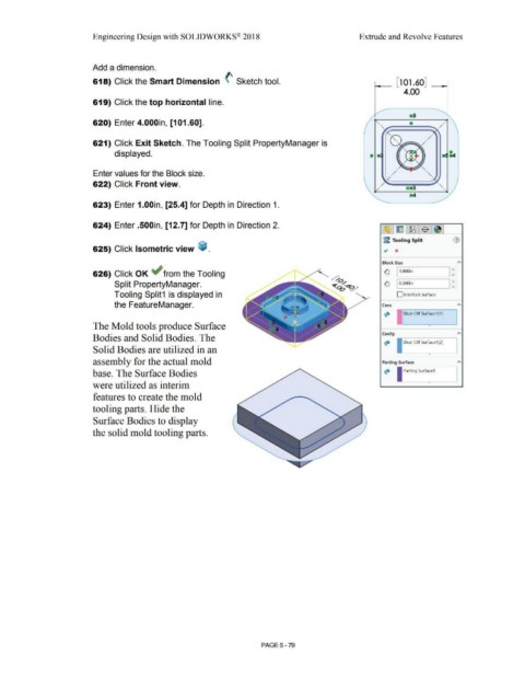
Add a dimension.
618) Click the Smart Dimension (' Sketch tool.
619) Click the top horizontal line.
620) Enter 4.000in, [101.60]. "------,/
•
621) Click Exit Sketch. The Tooling Split PropertyManager is •
displayed.
Enter values for the Block size.
_ ....
'
622) Click Front view.
'
623) Enter 1.00in, [25.4] for Depth in Direction 1.
624) Enter .500in, [12. 7] for Depth in Direction 2.
~-1 ~ 1.f!B.1 $ ~]
~ Tooling Split G)
625) Click Isometric view ~ . ~ x
Block Size A
626) Click OK ~ from the Tooling ~ 11.oooin I:
Split PropertyManager. ~ I O.SOOin I:
Tooling Split1 is displayed in D Interlock surface
the FeatureManager. Core A
~ Shut-Off Surface1[1]
The Mold tools produce Surface •
Cavity A
Bodies and Solid Bodies. The
~ I Shut-Off Surface1[2)
Solid Bodies are utilized in an
• -
assembly for the actual mold Parting Surface A
Parting Surface1
base. The Surface Bodies ~ I
were utilized as interim • ·-
features to create the mold
tooling parts. Hide the
Surface Bodies to display
the solid mold tooling parts.
PAGE5 - 79