
Page 446 - Subyek Computer Aided Design - [David Planchard] Engineering Design with SOLIDWORKS
P. 446
Extrude and Revolve Features Engineering Design with SOLIDWORKS® 2018
Fit the model to the Graphics window.
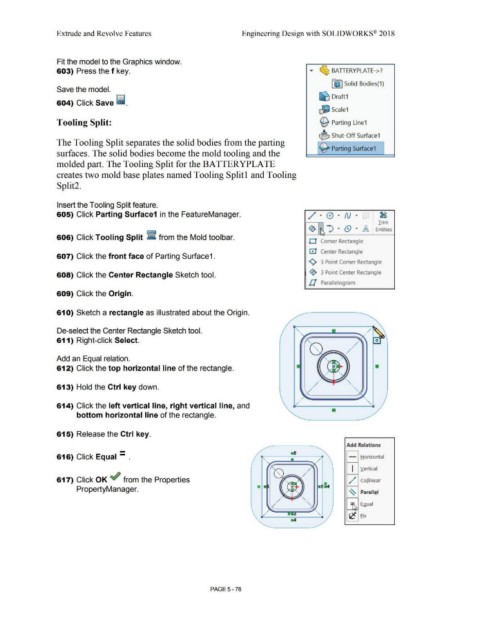
603) Press the f key. .,.. ~ BATTERYPLATE->?
Fe ·1 Solid Bodies(1)
Save the model.
604) Click Save ii. ~ Draft1
~ Scale1
Tooling Split: ~ Parting Line1
~ Shut-Off Surface1
The Tooling Split separates the solid bodies from the parting
~ Parting Surface1
surfaces. The solid bodies become the mold tooling and the
molded part. The Tooling Split for the BATTERYPLATE
creates two mold base plates named Tooling Splitl and Tooling
Split2.
Insert the Tooling Split feature.
605) Click Parting Surface1 in the FeatureManager. / · 0 · N • . ' . 8
•
•
•
•
Trim
' ") . (9 ·
~ IA Entities
•
606) Click Tooling Split ~ from the Mold toolbar.
O Corner Rectangle
0 Center Rectangle
607) Click the front face of Parting Surface1.
<>, 3 Point Comer Rectangle
608) Click the Center Rectangle Sketch tool. ~ 3 Point Center Rectangle
ll Parallelogram
609) Click the Origin.
61 O) Sketch a rectangle as illustrated about the Origin.
De-select the Center Rectangle Sketch tool.
611) Right-click Select.
/
;
=~ /
Add an Equal relation.
612) Click the top horizontal line of the rectangle.
613) Hold the Ctrl key down.
614) Click the left vertical line, right vertical line, and
bottom horizontal line of the rectangle.
615) Release the Ctrl key.
- Add Relations
616) Click Equal - . - Horizontal
•
I Vertical
617) Click OK ~ from the Properties / ,," Collinear
PropertyManager.
~
Parallel
:\ Egual
'c Eix
PAGE 5- 78