
Page 62 - Subyek Computer Aided Design - [David Planchard] Engineering Design with SOLIDWORKS
P. 62
Overview ofSOLIDWORKS® and the User Interface Engineering Design with SOLIDWORKS® 2018
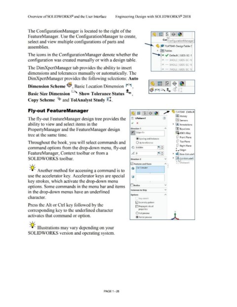
The ConfigurationManager is located to the right of the
F eatureManager. Use the ConfigurationManager to create, ~ : ~ I ~ 1$ ,~J
,.
~
Co,
select and view multiple configurations of parts and - Configuration Manager
assemblies. ~ ~ FLATBAR-DesignTable C
~ fil] Tables
...
The icons in the ConfigurationManager denote whether the *-r ~ Default [ GIDS-SC-1
configuration was created manually or with a design table. ~x 3HOLE [ GIDS-SC-1(
r SHOLE [ GIDS-SC-1 C
The DimXpertManager tab provides the ability to insert pX 7HOLE [ GIDS-SC-1C
dimensions and tolerances manually or automatically. The
DimXpertManager provides the following selections: Auto
~ ~~
Dimension Scheme ff;, Basic Location Dimension l+D+I ,
-$ r°1 °' :!:® I
Basic Size Dimension °' Show Tolerance Status :!:®,
Copy Scheme ~ and TolAnalyst Study ~I.
Fly-out FeatureManager A
~,~r~l$l~I ~ FLATBAR (Default.
® ~I History
The fly-out FeatureManager design tree provides the tg LPattern1 . tfi:J Sensors
ability to view and select items in the ~ x • IAJ Annotations
PropertyManager and the FeatureManager design Direction 1 "' ~ Equations
~ iEdge<1 > o-
i :::g6061 Alloy
tree at the same time. I
dJ Front Plane
@ spacing and instances
Throughout the book, you will select commands and O Up to reference dJ Top Plane
'
command options from the drop-down menu, fly-out 0i O.SOOin n:-B dJ Right Plane
l. Origin
FeatureManager, Context toolbar or from a o" # ~~ • ~ Boss-Extrude1
a• 9
'
SOLIDWORKS toolbar. Direction 2 v • ffij Cut-Extrude1
IP t , ~
c, c, _Pattern 1
!v'! Features and Faces
, 1 / "' •
®) Cut-Extrude1
-;Q~ Another method for accessing a command is to
use the accelerator key. Accelerator keys are special ~, •
key strokes, which activate the drop-down menu • I
options. Some commands in the menu bar and items 0Bodies v
Instances to Skip v
in the drop-down menus have an underlined
Options "'
character. Vary sketch
E2] Geometry pattern
Press the Alt or Ctrl key followed by the E2] Propagate visual
corresponding key to the underlined character properties y
O Full preview
activates that command or option. ' •
@ Partial preview ~
, 1 /
-;Q~ Illustrations may vary depending on your
SOLIDWORKS version and operating system.
PAGE 1 - 28