
Page 170 - Enhancing CAD Drawings with Photoshop
P. 170
4386.book Page 154 Monday, November 15, 2004 3:27 PM
154 CHAPTER 5 PRESENTING PLANS
Let’s begin by opening a new drawing file of a kitchen project.
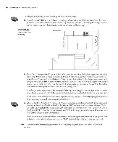
1. Launch AutoCAD if it is not already running and open the file Kitchen.dwg from the com-
panion CD. Figure 5.18 shows the cleaned-up drawing (see the “Cleaning Drawings” section
earlier in this chapter) that is ready to be transferred to Photoshop.
Figure 5.18
The kitchen CAD
drawing
2. Press Ctrl+P to open the Plot dialog box. Click OK if a warning dialog box appears indicating
a missing driver; you’ll select the correct driver in a moment. Just as you have done before,
select ImagePrinter.pc3 in the Printer/Plotter group, ImageSize in the Paper Size group, and
Images.ctb as the Plot Style Table. Set Plot Scale to 4 pixels = 1 unit as shown in Figure 5.16, earlier
in this chapter. Click the Preview button to display an image similar to Figure 5.18. Press Esc
twice to cancel the preview and close the Plot dialog box.
It is always wise to preview a plot manually before automating plot output. If you need to make
any adjustments, it is better to be aware of them before you output all the layers to image files.
Because our preview showed no obvious problems, we are ready to load the program and edit
it as necessary to match our current plot settings.
3. Choose Tools AutoLISP Visual LISP Editor. A new process launches with its own task but-
ton on the Windows Taskbar. Within the Visual LISP for AutoCAD window, choose File
Open File, navigate to the companion CD, and select the file lay2img.lsp. Figure 5.19 shows
the Visual LISP Editor that is built into AutoCAD with the program file open. There is a ver-
sion of this image in the color section.
Each parameter is color coded and commented with descriptive information. Change the Plot-
ted pixels = drawing units parameters to “4=1”, to match the settings you used in step 2.
TIP You can customize the plot parameters in the lay2img program to suit the needs of your own
projects.