
Page 301 - Fair, Geyer, and Okun's Water and wastewater engineering : water supply and wastewater removal
P. 301
JWCL344_ch07_230-264.qxd 8/2/10 8:44 PM Page 261
Problems/Questions 261
Table 7.22 Junction Information for Problem 7.5 Table 7.24 Pump Information for Problem 7.5
Junction Emitter Coefficient Elevation Head (ft) Head (m) Flow (gpm) Flow (L/min)
0.5
0.5
Label (gpm/psi ) (L/min/kPa ) (ft) (m)
170 51.8 0 0
J-1 — — 10 3.05 135 41.1 300 1,135.5
Hole 1 8 11.49 7 2.13 100 30.5 450 1,703.3
Hole 2 10 14.37 7 2.13
Hole 3 15 21.55 40 12.19
Hole 7
Hole 4 12 17.24 5 1.52 Hole 8
P-10 Hole 4
Hole 5 8 11.49 5 1.52 Hole 3
Hole 6 8 11.49 15 4.57 P-9
Hole 7 10 14.37 20 6.10 P-7
Hole 8 15 21.55 10 3.05 P-5
Hole 6
Hole 9 8 11.69 12 3.66 Hole 5 Hole 2
Table 7.23 Pipe Information for Problem 7.5 P-4
Hole 9 P-8 P-6
Diameter Diameter Length Length
Pipe Label (mm) (in) (m) (ft) R-1 P-11 Hole 1
P-3
P-1 100 4 3.05 10 P-1
PMP-1 P-2 J-1
P-2 100 4 304.8 1,000
P-3 100 4 243.8 800 Figure 7.16 Schematic for Problem 7.5
P-4 76 3 228.6 750
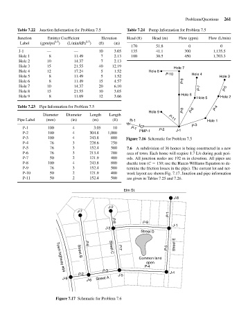
P-5 76 3 152.4 500 7.6 A subdivision of 36 homes is being constructed in a new
P-6 76 3 213.4 700 area of town. Each home will require 1.7 L/s during peak peri-
P-7 50 2 121.9 400 ods. All junction nodes are 192 m in elevation. All pipes are
P-8 100 4 243.8 800 ductile iron (C 130; use the Hazen-Williams Equation to de-
P-9 76 3 152.4 500 termine the friction losses in the pipe). The current lot and net-
P-10 50 2 121.9 400 work layout are shown Fig. 7.17. Junction and pipe information
P-11 50 2 152.4 500 are given in Tables 7.25 and 7.26.
Elm St.
J-8
J-2
J-7
P-1
P-9
P-8
J-1
J-3
Street D
Street E
P-5
P-6
P-7
Street C
Common land
Street B
open
P-4
P-3 J-4
Town highway #64
P-2 J-5
J-9 Street A
J-6
Figure 7.17 Schematic for Problem 7.6