
Page 298 - Fair, Geyer, and Okun's Water and wastewater engineering : water supply and wastewater removal
P. 298
JWCL344_ch07_230-264.qxd 8/2/10 8:44 PM Page 258
258 Chapter 7 Water Distribution Systems: Modeling and Computer Applications
Table 7.13 Pipe Information for Problem 7.2 highest node), and the top is approximately 20 ft (6.1 m) higher.
To avoid the cost of an elevated tank, this 80-ft-diameter (24.4-
Pipe Diameter (mm) Length (m)
m-diameter) tank is located on a hillside, 2,000 ft (610 m) away
P-1 250 1,525 from the main system. Assume that the tank starts with a water
P-2 150 300 surface elevation of 380 ft (115.8 m). The pump was originally
P-3 150 240 sized to deliver 300 gpm (1,135 L/min) with enough head to
P-4 150 275 pump against the tank when it is full. Three defining points on
P-5 150 245 the pump curve are as follows: 0 gpm at 200 ft of head; 300 gpm
P-6 200 230 at 180 ft of head; and 600 gpm at 150 ft of head (0 L/min at 610 m
of head; 1,135 L/min at 54.9 m of head; and 2,271 L/min at 45.7 m
of head). The pump elevation is assumed to be the same as the
Table 7.14 Junction Information for Problem 7.2
elevation at J-1, although the precise pump elevation is not cru-
Junction Elevation (m) Demand (L/min) cial to the analysis.
The system is to be analyzed under several demand condi-
J-1 55 950 tions with minimum and maximum pressure constraints.
J-2 49 1,060 During normal operations, the junction pressures should be be-
J-3 58 1,440 tween 35 psi and 80 psi (243 kPa and 555 kPa). Under fire flow
J-4 46 1,175 conditions, however, the minimum pressure is allowed to drop
J-5 44 980
to 20 psi (139 kPa). Fire protection is being considered both
with and without a sprinkler system.
Demand Alternatives: WaterGEMS enables you to store
7.3 A distribution system is needed to supply water to a resort multiple demand alternatives corresponding to various condi-
development for normal usage and emergency purposes (such as tions (such as average day, peak hour, etc.). This feature allows
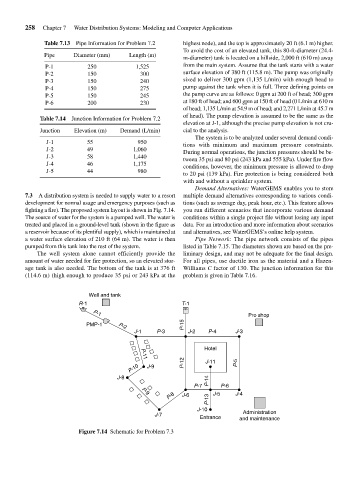
fighting a fire). The proposed system layout is shown in Fig. 7.14. you run different scenarios that incorporate various demand
The source of water for the system is a pumped well. The water is conditions within a single project file without losing any input
treated and placed in a ground-level tank (shown in the figure as data. For an introduction and more information about scenarios
a reservoir because of its plentiful supply), which is maintained at and alternatives, see WaterGEMS’s online help system.
a water surface elevation of 210 ft (64 m). The water is then Pipe Network: The pipe network consists of the pipes
pumped from this tank into the rest of the system. listed in Table 7.15. The diameters shown are based on the pre-
The well system alone cannot efficiently provide the liminary design, and may not be adequate for the final design.
amount of water needed for fire protection, so an elevated stor- For all pipes, use ductile iron as the material and a Hazen-
age tank is also needed. The bottom of the tank is at 376 ft Williams C factor of 130. The junction information for this
(114.6 m) (high enough to produce 35 psi or 243 kPa at the problem is given in Table 7.16.
Well and tank
R-1 T-1
Pro shop
P-1
PMP-1 P-2 P-15
J-1 P-3 J-2 P-4 J-3
Hotel
P-12 J-11 P-5
P-11
P-10 J-9
J-8 P-14
P-7 P-6
P-8 J-6 J-5 J-4
P-9
P-13
J-10
J-7 Administration
Entrance and maintenance
Figure 7.14 Schematic for Problem 7.3