
Page 294 - Fair, Geyer, and Okun's Water and wastewater engineering : water supply and wastewater removal
P. 294
JWCL344_ch07_230-264.qxd 8/2/10 8:44 PM Page 254
254 Chapter 7 Water Distribution Systems: Modeling and Computer Applications
events or design groups to be analyzed. Because we have only one design run in this
demonstration, you will not have to compare different potential design solutions. In many
cases, different solutions will need to be compared to evaluate which would be best for a
specific case. The left window helps organize these different solutions.
• On the Design Events tab, you can select the design criteria to be evaluated. In this case
there is only one choice.
• On the Design Groups tab, select the ductile-iron properties and cost that were entered.
The data is entered in the Design Option Group column. Because all designed pipe will
come from the same ductile-iron table, you can enter the data as a global edit. Right-click
the Design Option Group field and select Global Edit. Select the “New Ductile Iron
Pipe” in the Value window. Click OK; all of the Design Option Group fields should auto-
matically fill in.
• The Options tab allows the Darwin Designer parameters to be adjusted. In this case the
default values will be used.
• To start the run, click the Compute button in the Darwin Designer toolbar. When the
run is completed, close the Designing… window. The top three solutions will be listed
under the “New Optimized Design Run” in the left window.
Answer
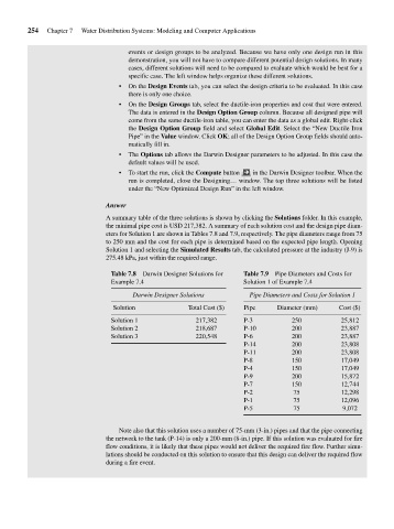
A summary table of the three solutions is shown by clicking the Solutions folder. In this example,
the minimal pipe cost is USD 217,382. A summary of each solution cost and the design pipe diam-
eters for Solution 1 are shown in Tables 7.8 and 7.9, respectively. The pipe diameters range from 75
to 250 mm and the cost for each pipe is determined based on the expected pipe length. Opening
Solution 1 and selecting the Simulated Results tab, the calculated pressure at the industry (J-9) is
275.48 kPa, just within the required range.
Table 7.8 Darwin Designer Solutions for Table 7.9 Pipe Diameters and Costs for
Example 7.4 Solution 1 of Example 7.4
Darwin Designer Solutions Pipe Diameters and Costs for Solution 1
Solution Total Cost ($) Pipe Diameter (mm) Cost ($)
Solution 1 217,382 P-3 250 25,812
Solution 2 218,687 P-10 200 23,887
Solution 3 220,548 P-6 200 23,887
P-14 200 23,808
P-11 200 23,808
P-8 150 17,049
P-4 150 17,049
P-9 200 15,872
P-7 150 12,744
P-2 75 12,298
P-1 75 12,096
P-5 75 9,072
Note also that this solution uses a number of 75-mm (3-in.) pipes and that the pipe connecting
the network to the tank (P-14) is only a 200-mm (8-in.) pipe. If this solution was evaluated for fire
flow conditions, it is likely that these pipes would not deliver the required fire flow. Further simu-
lations should be conducted on this solution to ensure that this design can deliver the required flow
during a fire event.