
Page 52 - Finite Element Modeling and Simulations with ANSYS Workbench
P. 52
Bars and Trusses 37
Assemble the structure FE equation,
u 1 v 1 u 2 v 2 u 3 v 3
1 1 − 1 − 1 0 0 u 1 F F X
1
− −
1
1 1 1 1 0 0 1 v F Y
EA − 1 − 1 2 0 − 1 1 u 2 = F X
2
2 L − 1 − 1 0 2 1 − 1 2 v F Y
2
0 0 − 1 1 1 − 1 u 3 F X
3
0 0 0 1 − 1 − 1 1 v
3
3 F Y
Load and boundary conditions (BCs):
u 1 = v 1 = u 3 = v 3 = 0, F X2 = P 1 , F Y2 =
P 2
Condensed FE equation,
EA 2 0 u 2 P 1
P 2
2 L 0 2 v 2 =
Solving this, we obtain the displacement of node 2,
u 2 L
P 1
=
v 2 EA P 2
Using Equation 2.34, we calculate the stresses in the two bars,
0
0
E 2 L 2
2 P
σ= − 1 −1 1 1 = ( 1 P + )
1
1 P
L 2 EA 2A
2 P
1 P
2 P
=
σ= E 2 1 −1 −1 1 L 2 ( 1 P − )
2 P
2
L 2 EA 2A
0
0
Check the results: Again, we need to check the equilibrium conditions, symmetry, anti-
symmetry, and so on, of the FEA results.
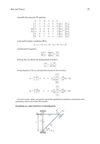
EXAMPLE 2.4: (MULTIPOINT CONSTRAINT)
y
x
P 3
2 2
1
L Y
3
45°
1
X