
Page 53 - Finite Element Modeling and Simulations with ANSYS Workbench
P. 53
38 Finite Element Modeling and Simulation with ANSYS Workbench
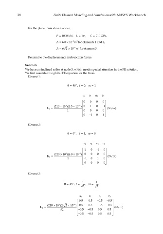
For the plane truss shown above,
P = 1000 kN, L = 1 m, E = 210 GPa,
2
A = 60 × 10 −4 m for elements 1 and 2,
.
A = 62 × 10 −4 m 2 for element 3.
Determine the displacements and reaction forces.
Solution
We have an inclined roller at node 3, which needs special attention in the FE solution.
We first assemble the global FE equation for the truss.
Element 1:
o
θ= 90 , l = 0, m = 1
u 1 v 1 u 2 v 2
0 0 0 0
4
9
60 ×
−
( 210 × 10 )(. 10 ) 0 1 0 − 1
1 k = (N/m )
1 0 0 0 0
−
0 1 0 1
Element 2:
o
θ= 0 , l = 1, m = 0
u 2 v 2 u 3 v 3
1 0 − 1 0
4
−
60 ×
( 210 × 10 )(. 10 ) 0 0 0 0
9
2 k = (N/m )
1 − 1 0 1 0
0 0 0 0
Element 3:
1 1
o
θ= 45 , l = , m =
2 2
u 1 v 1 u 3 v 3
05 05 − 05 − 05
.
.
.
.
4
−
.
.
.
.
9
( 210 × 10 )( 62 × 10 ) 05 05 − 05 − 05
3 k = (N/m )
.
2 − − 05. −05. 05 05
.
.
.
− 05. −05. 05 05 