
Page 48 - Finite Element Modeling and Simulations with ANSYS Workbench
P. 48
Bars and Trusses 33
2 − 2 0 u 1 F 1
EA − 2 3 − 1 u 2 =
F 2
L − 1
0 1 u 3 F 3
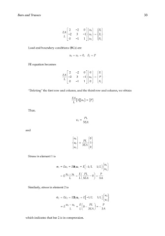
Load and boundary conditions (BCs) are
u 1 = u 3 = 0, F 2 = P
FE equation becomes
2 − 2 0 0 F 1
EA − 2 3 −
P
L 1 u 2 =
0 − 1 1 0 F 3
“Deleting” the first row and column, and the third row and column, we obtain
EA 3 []{} P
u 2 = {}
L
Thus,
PL
u 2 =
3 EA
and
u 1 0
PL
u 2 = 1
3 EA
0
u 3
Stress in element 1 is
1 u
σ= E ε= EBu = E − 1 L 1 L
/
/
1
1
11
2 u
2 u − u 1 E PL P
= E = − 0 =
L L 3EA 3 A
Similarly, stress in element 2 is
2 u
σ= ε= EBu 2 = E − 1 L 1 L
E
/
/
2
2
2
3 u
3 u − u 2 E PL P
= E = 0 − =−
L L 3EA 3 A
which indicates that bar 2 is in compression.